
Trailing edge of an aircraft aerodynamic surface

a technology of aerodynamic surface and trailing edge, which is applied in the direction of sandwich construction, transportation and packaging, wing shapes, etc., can solve the problems of increasing the drag of the profile, affecting the aerodynamic profile of the trailing edge, and affecting the aerodynamic profile of the aforementioned trailing edge, so as to reduce the weight of the lightweight part

Active Publication Date: 2014-11-20
AIRBUS OPERATIONS SL
View PDF9 Cites 22 Cited by
  • Summary
  • Abstract
  • Description
  • Claims
  • Application Information

AI Technical Summary

Benefits of technology

The present invention introduces a new way to design the trail edge of several aerodynamic surfaces in an aircraft. These surfaces include vertical and horizontal stabilizers, elevators, wings, flaps, and ailerons. By using this new design, aircraft can have improved efficiency and performance.

Problems solved by technology

When the upper skin and the lower skin of said aircraft structure are made of sandwich type composite materials, due to the minimum core thickness requirement for each skin, there is a change in the slope of the upper skin and the lower skin, which worsens the aerodynamic profile of the aforementioned trailing edge.
This falling off increases the profile drag and the falling off is an esthetic drawback that is the cause of many complaints from airlines.

Method used


Image

  • Trailing edge of an aircraft aerodynamic surface
  • Trailing edge of an aircraft aerodynamic surface
  • Trailing edge of an aircraft aerodynamic surface

Examples


Embodiment Construction

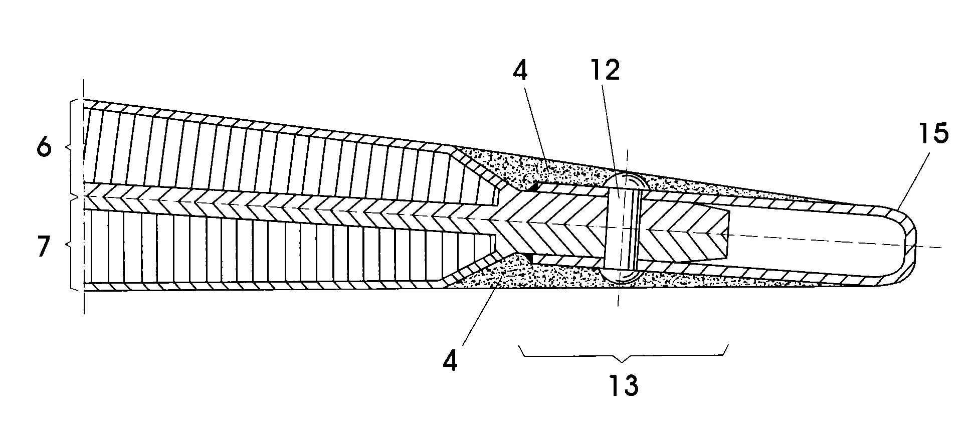
[0041]The invention discloses a new trailing edge (2) of an aircraft aerodynamic surface comprising an upper skin (6), a lower skin (7) and a new lightweight part (1) to join the upper and lower skins (6, 7).

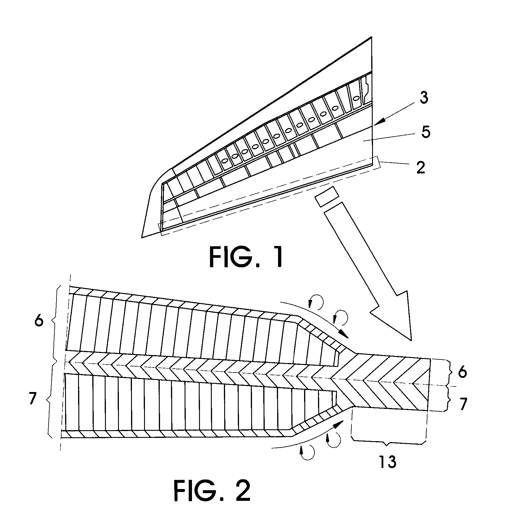
[0042]FIG. 1 shows a horizontal tail plane (HTP) (3) where the trailing edge (2) of an elevator (5) of said horizontal tail plane (HTP) (3) is highlighted.

[0043]FIG. 2 shows a view of a cross section of the trailing edge (2) of the elevator (5) of the HTP (3), where said trailing edge (2) is formed by the joint of the upper skin (6) and the lower skin (7).

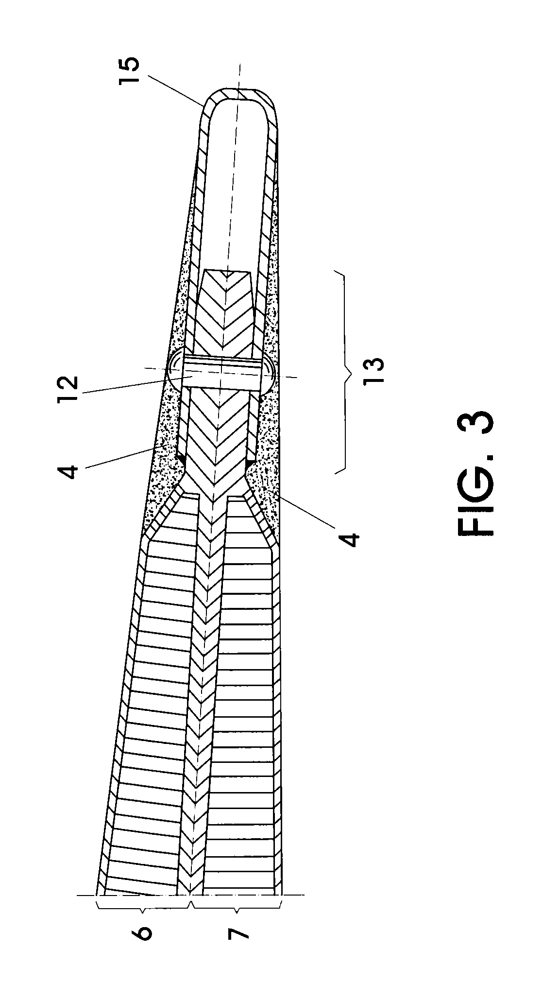
[0044]Due to the minimum core thickness requirement for each of the skins which make up the trailing edge (2) of an aircraft elevator (5), there is a change in the slope of said upper and lower skins (6, 7), which worsens the aerodynamic profile of the trailing edge (2).

[0045]FIG. 3 shows an elevator (5) trailing edge (2) structure currently used. Said structure comprises a “U”-shaped metallic sheet (15) fastened to the upper a...


PUM


Abstract

The invention discloses a trailing edge (2) of an aircraft aerodynamic surface, which comprises an upper skin (6) and a lower skin (7), being the upper and lower skins (6, 7) made of composite material. In the trailing edge (2) a lightweight part (1) is assembled at an end section (13) of the upper and lower skins (6, 7). The lightweight part (1) is covered by a metallic sheet (8), and has a “V”-shaped cross section with arms and peak, where the peak of the “V”-shaped cross section has a rounded shape and is located opposite the end section (13) of the upper and lower skins (6, 7).

Description

OBJECT OF THE INVENTION[0001]The present invention discloses a new design of the trailing edge of an aircraft aerodynamic surface, said design is used for the trailing edge of a vertical stabilizer, a rudder, for the trailing edge of a horizontal stabilizer, an elevator, for the trailing edge of a wing, for the trailing edge of a flap and in the trailing edge of an aileron in an aircraft.BACKGROUND OF THE INVENTION[0002]The skins of an elevator, in Long Range (LR) & Single Aisle (SA) type aircraft, are manufactured with sandwich type composite materials.[0003]Sandwich type composite material skins are manufactured by attaching two thin, but stiff skins (typically made from carbon fibre reinforced plastic laminates) to a lightweight but thick core (usually open and closed-cell structured foams). The core must have a minimum thickness in order to withstand the pressure transferred by the carbon fibre reinforced laminates during the curing cycle wherein a high temperature and pressure ...

Claims


Application Information

Patent Timeline
Patent Type & Authority Applications(United States)
IPC IPC(8): B64C3/28B64C5/00
CPCB64C5/00B64C3/28B64C3/20B64C2003/147
Inventor DE GREGORIO HURTADO, YOLANDABALSA GONZALEZ, ALBERTO
Owner AIRBUS OPERATIONS SL
Learn More