Wireless power feeding system and wireless power feeding method

a power feeding system and wireless technology, applied in transportation and packaging, rail devices, battery/cell propulsion, etc., can solve the problems of coil diameter increase, drawback of above-described magnetic resonance system, etc., and achieve high-efficiency space power transmission and long distance

Active Publication Date: 2014-11-20
NEC CORP
View PDF5 Cites 44 Cited by
  • Summary
  • Abstract
  • Description
  • Claims
  • Application Information

AI Technical Summary

Benefits of technology

[0017]According to the present invention, it is possible to provide a wireless power feeding system and a wireless power feeding method capable of long distance and highly efficient space transmission of power.

Problems solved by technology

However, the inventors have found that there is a drawback in the above-described magnetic resonance system.
However, increasing the wavelength results in an increase in the coil diameter.
Particularly, because the receiving coil is closely related to the size of equipment on which it is mounted, there are almost no applications for a receiving coil with a diameter of several meters or more under the present conditions.

Method used


Image

  • Wireless power feeding system and wireless power feeding method
  • Wireless power feeding system and wireless power feeding method
  • Wireless power feeding system and wireless power feeding method

Examples


first exemplary embodiment

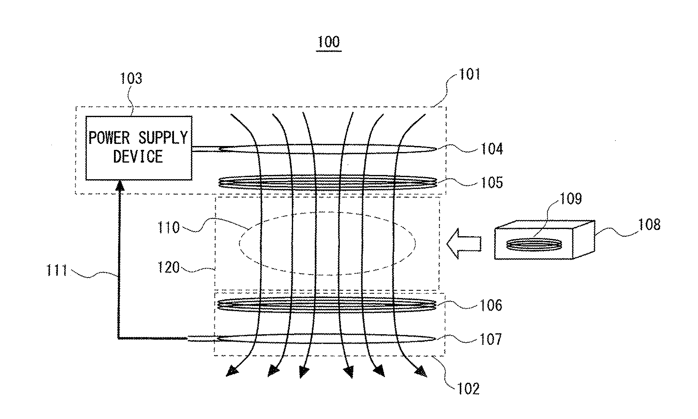
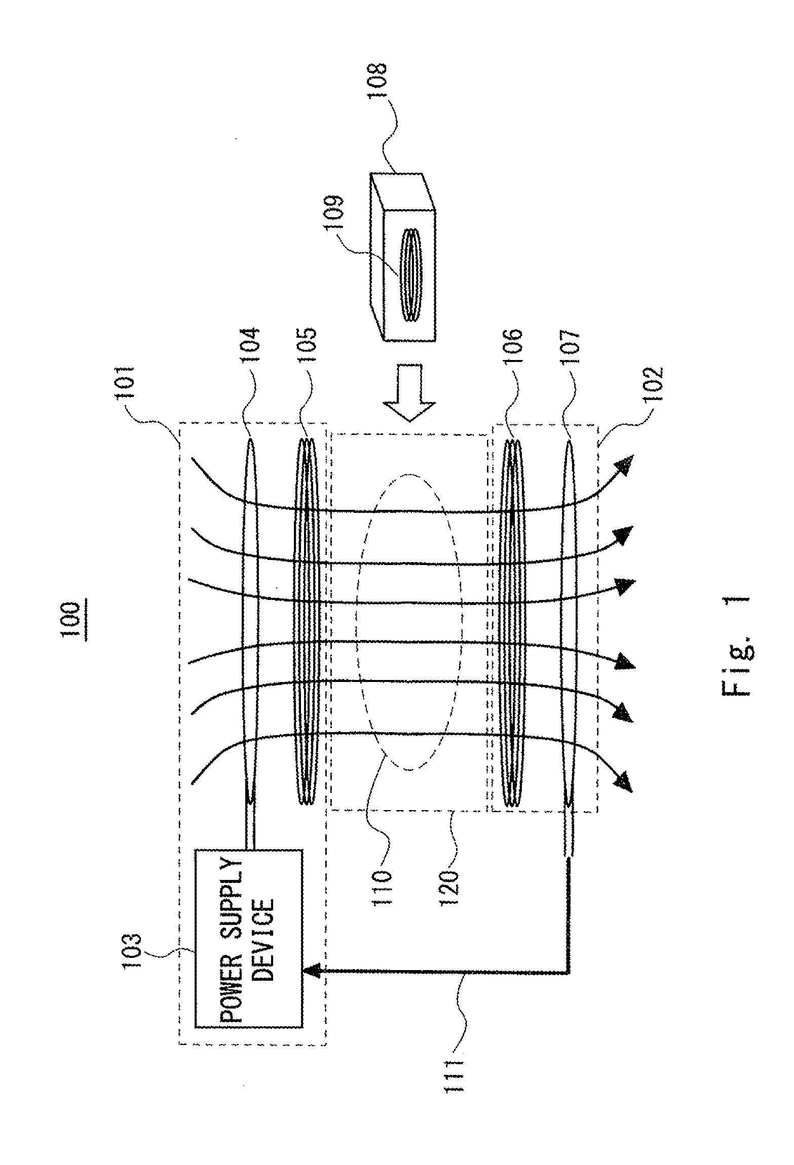
[0033]First, a wireless power feeding system 100 according to a first exemplary embodiment of the invention is described hereinafter. FIG. 1 is a front view schematically showing the configuration of the wireless power feeding system 100 according to the first exemplary embodiment. As shown in FIG. 1, the wireless power feeding system 100 includes a power transmitter 101 and a power receiver 102. The power transmitter 101 is a device that wirelessly transmits power. The power receiver 102 is a device that receives power from the power transmitter 101. In the wireless power feeding system 100, an electromagnetic field is created in the space between the power transmitter 101 and the power receiver 102 by power transmission between the power transmitter 101 and the power receiver 102. In other words, power transmission is performed by means of magnetic resonance between the power transmitter 101 and the power receiver 102. Note that FIG. 1 schematically shows magnetic field lines 110 ...

example 1

[0052]A wireless power feeding system according to the example 1 of the present invention is described hereinafter. The example 1 relates to a wireless power feeding system 1001, which is an example in the case where the wireless power feeding system 100 is applied to a room in a building. FIG. 4 is a front view schematically showing the configuration example of the wireless power feeding system 1001 according to the example 1. As shown in FIG. 4, the power transmitter 101 is mounted on the backside of the ceiling of a room 201, and the power receiver 102 is mounted under the floor of the room 201. To simplify the drawing, the magnetic field lines 110 are shown by dotted lines in FIG. 4. In this example, the diameter of the coils of the power transmitter 101 and the power receiver 102 is 15 m, and the distance between the coils is 5 m. Further, the resonant frequency is 1 MHz. The transmitter primary coil 104 and the receiver primary coil 107 are circular single layer coils, and the...

second exemplary embodiment

[0054]Next, a wireless power feeding system 200 according to a second exemplary embodiment of the invention is described hereinafter. The wireless power feeding system 200 is a modified example of the wireless power feeding system 100. FIG. 5 is a front view schematically showing the configuration of the wireless power feeding system 200 according to the second exemplary embodiment. As shown in FIG. 5, the power transmitter 101 is placed to surround the space 120. The other configuration of the wireless power feeding system 200 is the same as that of the wireless power feeding system 100 and not redundantly described.

[0055]In the wireless power feeding system 200, an electromagnetic field in the space between the power transmitter 101 and the power receiver 102 can be enhanced just like in the wireless power feeding system 100, though the position of the power transmitter 101 is different. The power receiving body 108 inserted in the space 120 can thereby receive power with high eff...


PUM

PropertyMeasurementUnit
poweraaaaaaaaaa
poweraaaaaaaaaa
transmission distanceaaaaaaaaaa

Abstract

A wireless power feeding system capable of long distance and highly efficient space transmission of power is provided. A wireless power feeding system includes a power transmitter, a power receiver, and a power receiving body. The power transmitter generates electromagnetic waves. The power receiver is supplied with power by means of the electromagnetic waves received from the power transmitter using a magnetic field resonance phenomenon. The power receiving body is inserted into an electromagnetic field created by the power transmitter and the power receiver, and receives power by means of the electromagnetic field.

Description

TECHNICAL FIELD [0001]The present invention relates to a wireless power feeding system and a wireless power feeding method for wirelessly transmitting power.BACKGROUND ART[0002]Wireless power transmission, which is also called non-contact charging technology, is applied to various products today. Known forms of wireless power transmission are using electromagnetic induction and radio waves. Wireless power transmission via electromagnetic induction is triggered by the discovery of Faraday's law in 1831, followed by the invention of the transformer in 1836. The transmission distance in the electromagnetic induction-type wireless power transmission is several mm or less, and the operating frequency is several hundred KHz or less in many cases. The electromagnetic induction-type is characterized in that the transmission distance is short and there is no leakage of the magnetic field, though the amount of power transmission depends on design. The wireless power transmission requires no c...

Claims


Application Information

Patent Timeline
Patent Type & Authority Applications(United States)
IPC IPC(8): H02J17/00B60L11/18H02J7/02H01F38/14H02J5/00
CPCH02J17/00H01F38/14B60L11/182H02J7/025H02J5/005B60M7/00B60L50/60Y02T10/70H02J50/50H02J50/05H02J50/12
Inventor TSUJI, MASAYOSHIHATTORI, WATARUTANOMURA, MASAHIROYOSHIDA, SHUHEI
Owner NEC CORP
Why Eureka
Try Eureka