
Low profile pump with the ability to be mounted in various configurations

a low-profile, pump technology, applied in the direction of positive displacement liquid engine, valve construction, liquid fuel engine, etc., can solve the problems of known pumping device flexibility, and reducing the overall attractiveness and fit for purpos

Active Publication Date: 2014-11-20
FLOW CONTROL LLC
View PDF108 Cites 19 Cited by
  • Summary
  • Abstract
  • Description
  • Claims
  • Application Information

AI Technical Summary

Benefits of technology

The present invention is a pump that can pump liquid using a pick-up scoop or nozzle. It has a flexible arrangement of a discharge port that can be rotated into many positions on multiple axes. This allows for more flexibility and control of the pump's output, making it more efficient and effective than other pumps of this nature. The unique rotational orientation of the water level sensor also allows for a lower water level sensing setting. Overall, the pump has technical effects that make it more efficient, flexible, and capable of pacing liquid in a more precise manner.

Problems solved by technology

Known pumping devices are limited in the angles or flexibility in the discharge outlet of the pump reducing the overall attractiveness and fit for the purpose that they are intended to achieve.
Another limitation is in the switching options that are available.

Method used


Image

  • Low profile pump with the ability to be mounted in various configurations
  • Low profile pump with the ability to be mounted in various configurations
  • Low profile pump with the ability to be mounted in various configurations

Examples


Embodiment Construction

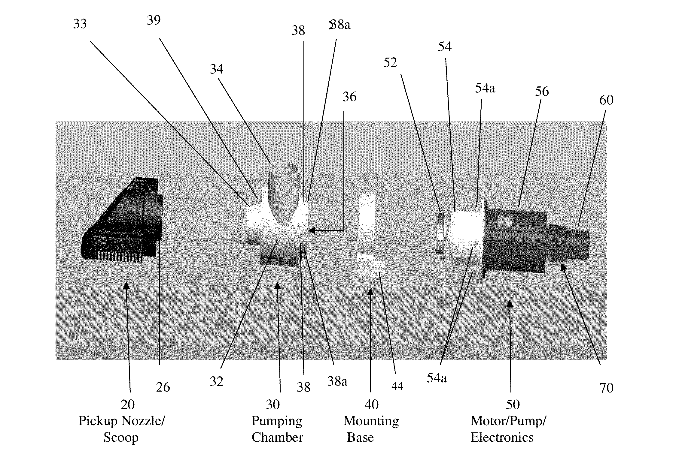
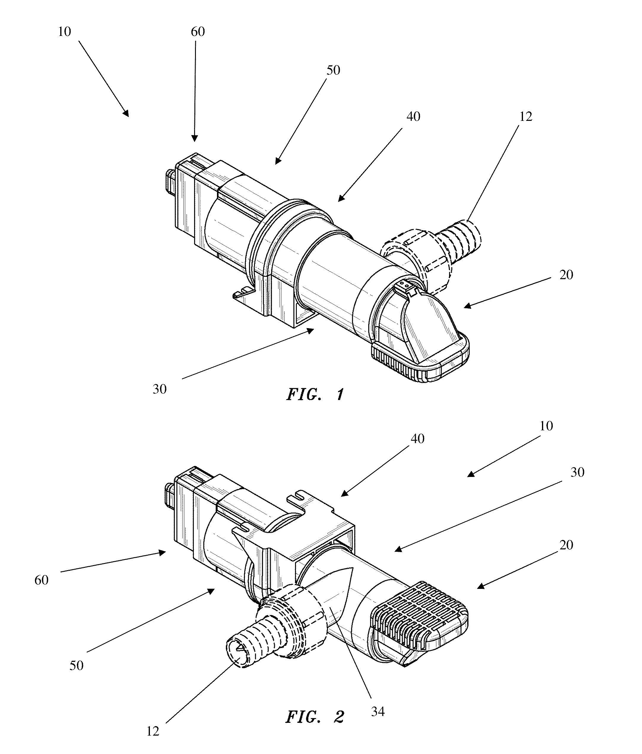
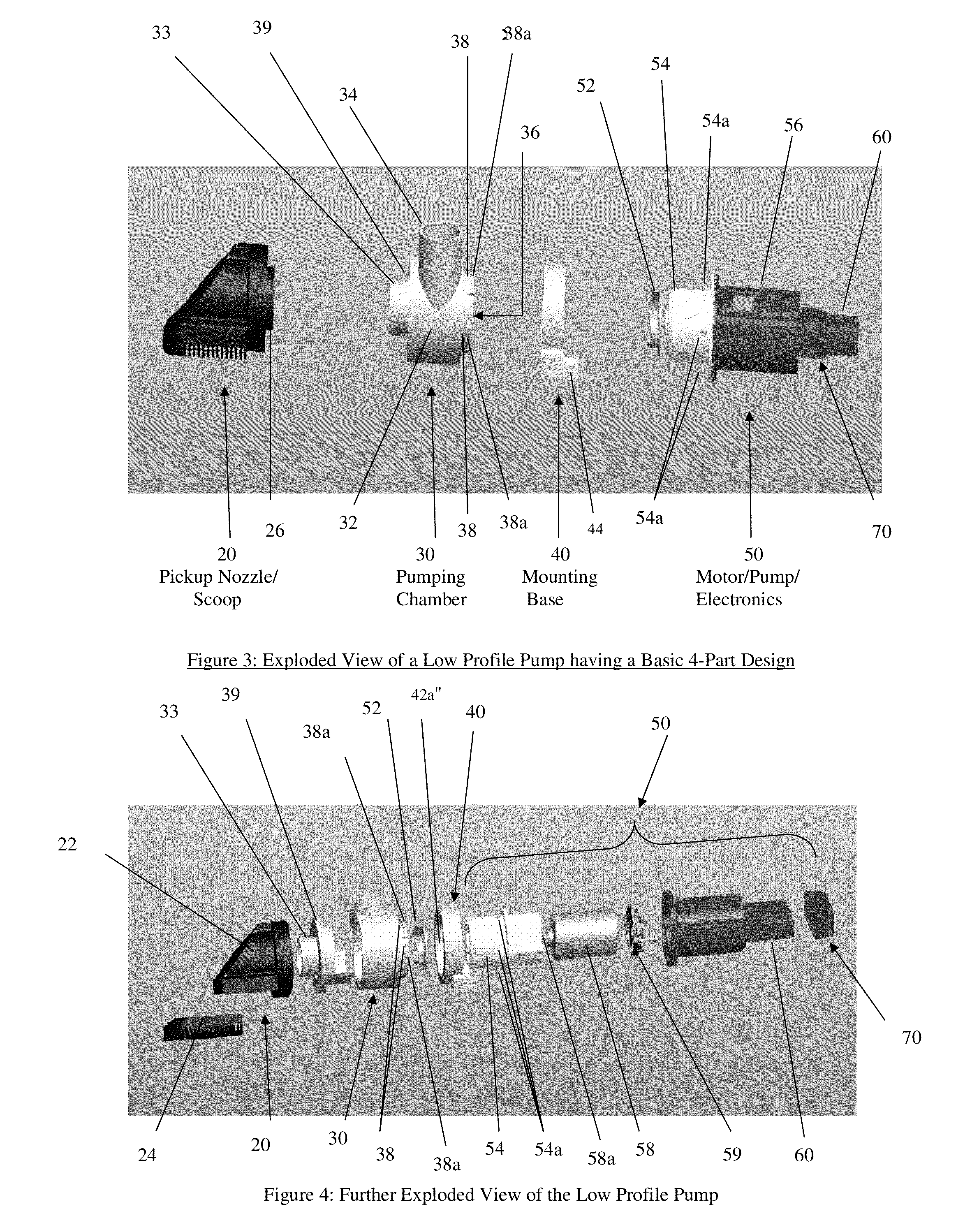
[0031]FIGS. 1-5 show a low profile pumping system according to some embodiments of the present invention generally indicated as 10, having four basic parts or components, including a pickup nozzle / scoop generally indicated as 20, a pumping chamber generally indicated as 30, a mounting base generally indicated as 40, a motor / pump / electronics assembly generally indicated as 50 and a switch assembly, circuit or arrangement generally indicated as 60. The low profile pump 10 may take the form of a bilge pump for mounting in the bilge of a boat or vessel for pumping water from the bilge out of the boat or vessel. In FIGS. 1-2, the pump 10 is shown with an optional adapter 12 in dashed lines that may be configured on a discharge port or outlet 34 of the pumping chamber 30 depending on the particular application. For example, the adapter 12 may be configured with suitable hosing (not shown) for use as a conduit for providing the fluid being pumped, e.g., out of the boat or vessel. The mount...


PUM


Abstract

A pumping system featuring a pump chamber configured with a central portion having a tangential outlet, and configured with a tubular coupling end portion having inwardly flexible rim portions on one side; and a mounting base, having a circular portion with an inner circumferential rim configured to receive and engage the inwardly flexible rim portions of the tubular coupling portion of the pump chamber so as to be rotationally coupled to the pumping chamber so that the pumping chamber may be rotated 360° in relation to the mounting base.

Description

CROSS REFERENCE TO RELATED APPLICATION[0001]This application claims benefit to provisional patent application No. 61 / 803,265, filed 19 Mar. 2013, as well as provisional patent application No. 61 / 824,151, filed 16 May 2013, which are both hereby incorporated by reference in its entirety.BACKGROUND OF THE INVENTION[0002]1. Field of the Invention[0003]The present invention relates to a pump or pumping system, including a bilge pump for mounting in a vessel.[0004]2. Brief Description of Related Art[0005]Pumps are known and used to move bilge water or work in confined areas with hoses attached for directing the water to a desired exit point or area. A mechanical or electronic switching method is typically used to turn the pump on / off.[0006]Known pumping devices are limited in the angles or flexibility in the discharge outlet of the pump reducing the overall attractiveness and fit for the purpose that they are intended to achieve. Another limitation is in the switching options that are av...

Claims


Application Information

Patent Timeline
IPC IPC(8): F04D1/12F04D15/02F04D29/46
CPCF04D1/12F04D15/0218F04D29/466F04D13/021F04D13/086F04D29/605F04D29/4293F05D2260/33B63B13/00F04D13/0686F04D29/406
Inventor GELL, III, WILLIAM A.LOPES, JEFFREY D.ESTRADA, JESUSMOORMANN, RANDALL H.
Owner FLOW CONTROL LLC
Learn More