
Modulation/demodulation method, demodulation apparatus, and code modulation method

a demodulation apparatus and code technology, applied in the direction of coding, individual digit conversion, code conversion, etc., can solve the problems of ineffective utilization of recording media and rapid difficulty in symbol discrimination, so as to prevent excessive consecration of 0 or 1, enhance linear recording density, and enhance linear recording density

Inactive Publication Date: 2014-11-20
HITACHI CONSUMER ELECTRONICS CORP +1
View PDF1 Cites 1 Cited by
  • Summary
  • Abstract
  • Description
  • Claims
  • Application Information

AI Technical Summary

Benefits of technology

The patent text describes a method of using code modulation to improve the performance of optical disks. Code modulation helps prevent errors and improve the density of information recorded on the disk. The text also mentions that using a specific code called 1-7PP can increase the linear recording density by about 4 / 3 compared to not using the code modulation. Additionally, the text explains how the modulation code can reduce the occurrence of burst errors, which are long-lasting errors caused by demodulation errors. The patent text also mentions that the use of the modulation code can help an optical disk drive return from demodulation errors caused by burst errors.

Problems solved by technology

Therefore, when binary data (referred to as user data in the present specification) to be recorded is recorded to correspond to a presence of a recording mark, symbol discrimination becomes rapidly difficult due to intersymbol interference between adjacent bits when an interval of bits to be recorded becomes smaller than the diameter of the optical spot.
As a result, the resolution of the recording medium cannot effectively be utilized.

Method used


Image

  • Modulation/demodulation method, demodulation apparatus, and code modulation method
  • Modulation/demodulation method, demodulation apparatus, and code modulation method
  • Modulation/demodulation method, demodulation apparatus, and code modulation method

Examples


Embodiment Construction

Asymmetric Modulation and Demodulation

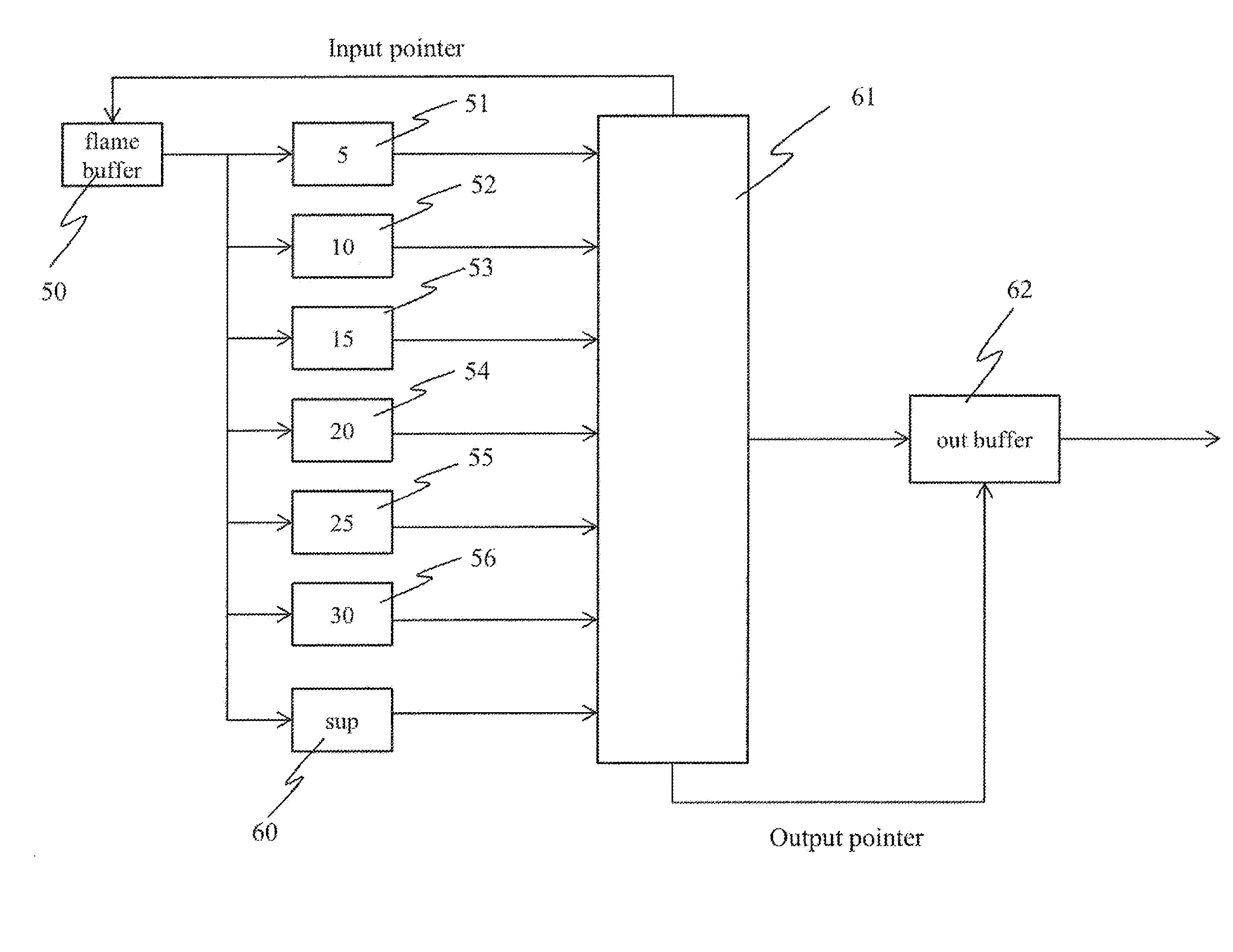
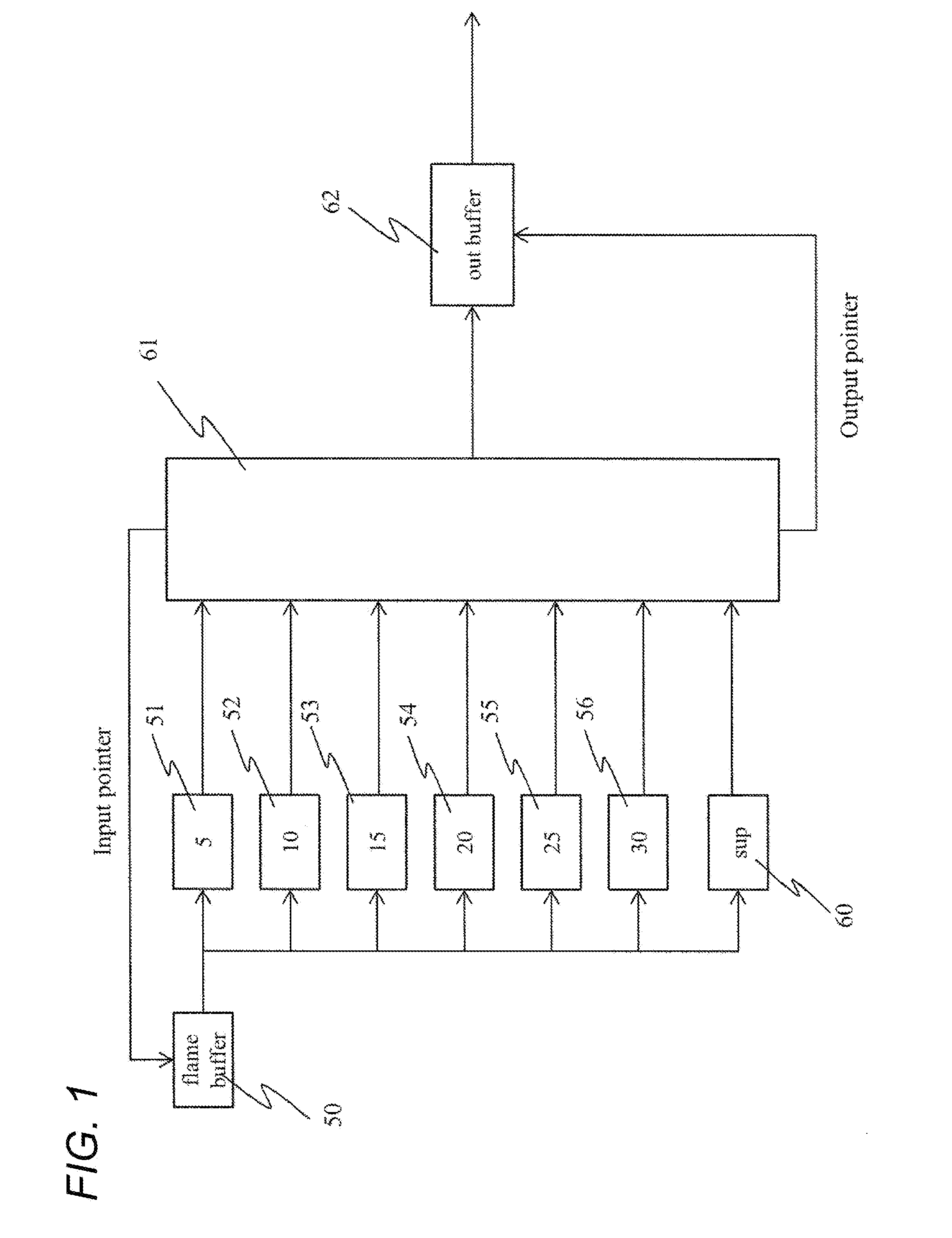
[0050]A countermeasure based upon the present invention against an occurrence of a demodulation error due to an occurrence of a burst error in the problems described above will be described. Firstly, an asymmetric conversion is used. This will be described with reference to FIG. 7 illustrating an example of a pattern. In this example, a burst error occurs in which all edges in a channel word are shifted to the right by 1 channel bit. If the channel bit pattern generated as a result of the burst error is listed in the conversion table, the demodulation process after this part can be continued, although the result of the demodulation includes an error. The problem is that the demodulation process cannot be continued since the channel bit pattern generated as a result of the burst error is not listed on the conversion table. In view of this, a supplementary pattern set 41 having a supplementary pattern 40, which is the channel bit pattern generated...


PUM


Abstract

Patterns that might be generated due to a burst error are prepared beforehand. These patterns are formed by shifting all “1”s in an original channel word. A list of these patterns generated as described above is retrieved in parallel with a general conversion table during demodulation. When the demodulation is interrupted due to the burst error, the result of the retrieval of the previous pattern is referred to, and when there is a hit, the error is regarded as the burst error of the original channel word, and the demodulation is continued.

Description

CROSS-REFERENCE TO RELATED APPLICATIONS[0001]This application claims the priority of Japanese Patent Application No. 2013-105742, filed on May 20, 2013, which is incorporated herein by reference in its entirety.BACKGROUND OF THE INVENTION[0002]1. Field of the Invention[0003]The present invention relates to a modulation / demodulation method of a signal, a demodulation apparatus, and a code modulation method, and more particularly to a method of recording and reproducing information with high density by using light.[0004]2. Description of the Related Art[0005]Some terms in the description below are those used for Blu-ray (registered trademark) Disc (BD). These terms are likely to be described as another term in a system other than the BD. However, a person skilled in the art could have easily replaced these terms.[0006]There are some systems for increasing a storage capacity of an optical disk. One of them is a code modulation described in U.S. Pat. No. 5,400,023 and JP-2003-273743-A. ...

Claims


Application Information

Patent Timeline
Patent Type & Authority Applications(United States)
IPC IPC(8): H03M13/00
CPCH03M13/6325H03M5/14H03M7/40H03M7/6052
Inventor KIKUGAWA, ATSUSHI
Owner HITACHI CONSUMER ELECTRONICS CORP
Learn More