Method for manufacturing a magnetic head for perpendicular recording
a manufacturing method and technology for perpendicular recording, applied in the manufacture of head surfaces, instruments, record information storage, etc., can solve the problems of large obstacles to high density recording implementation, and achieve the effects of improving the curvature of the magnetic transition, reducing the expansion of the write field, and improving the shape of the write field
- Summary
- Abstract
- Description
- Claims
- Application Information
AI Technical Summary
Benefits of technology
Problems solved by technology
Method used
Image
Examples
example 1
[0028]Below, the present invention will be described by reference to drawings. FIG. 3(A) is a schematic diagram of a magnetic disk storage apparatus utilizing the present invention (wherein the scaling factor of the diagram is not constant). FIG. 3(B) is an enlarged view of a magnetic head slider 13 of FIG. 3(A). FIG. 3(C) is an enlarged view of a magnetic head element 14 of FIG. 3(B). The magnetic disk storage apparatus performs writing and reading of a magnetization signal on a magnetic disk 11 by means of the magnetic head 14 mounted on the slider 13 fixed on the tip of a suspension arm 12. FIG. 4 is a schematic diagram for showing the relationship between a magnetic head for perpendicular recording and a magnetic disk (wherein the scaling factor of the diagram is not constant). FIG. 5 is a schematic diagram for showing perpendicular recording. The magnetic field generated from a main pole forms a magnetic circuit in which the magnetic flux passes through a recording layer and an...
example 2
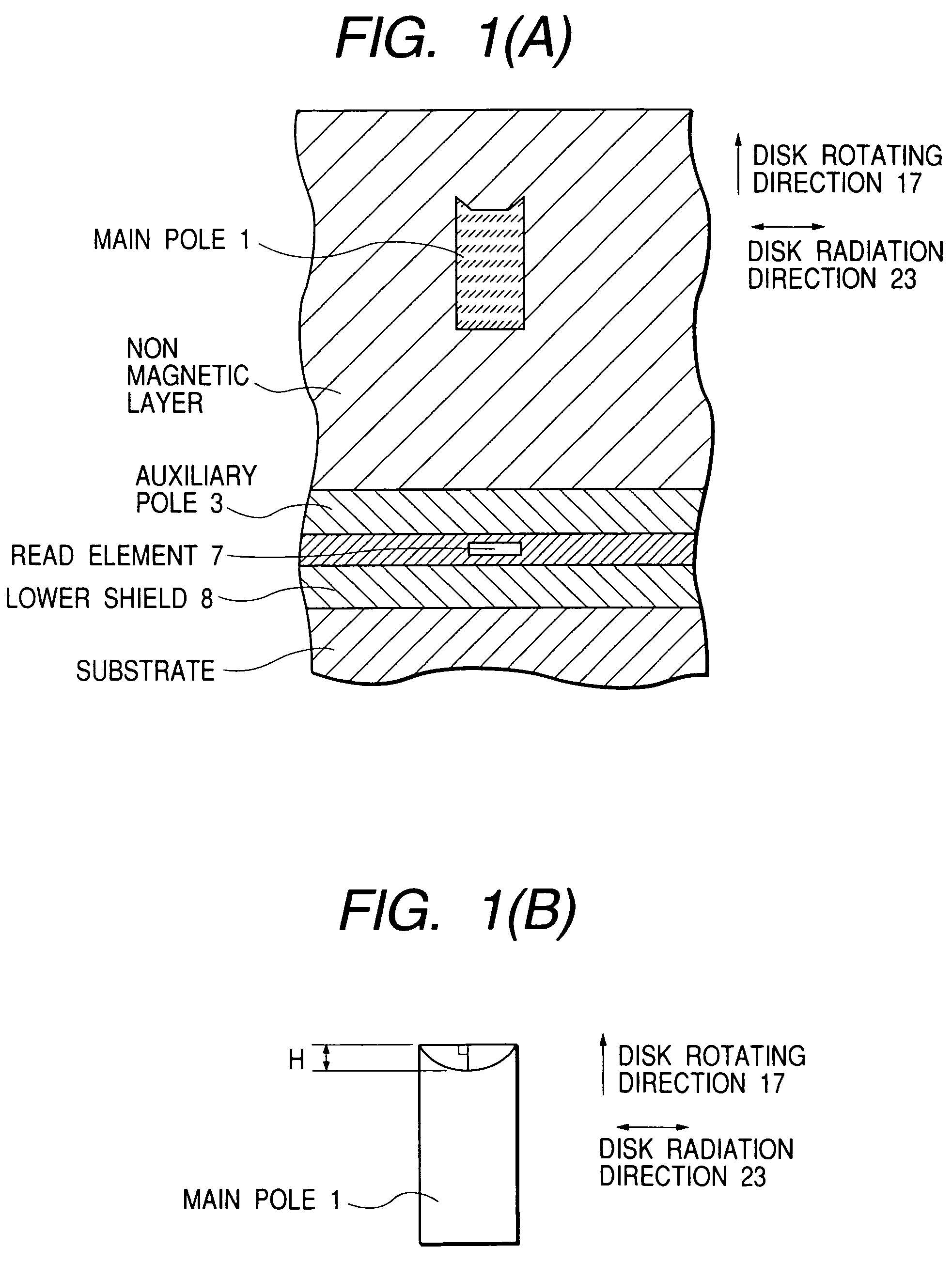
[0032]In Example 1, the shape of the recess provided on the trailing side of the main pole has been the shape of a curve. However, the effect of improving the curvature of the shape of magnetic transition can also be obtained even with other shapes. For example, the shape of the recess may also be trapezoid as shown in FIG. 8(A). Alternatively, the shape of the recess may also be triangle or rectangle as shown in FIG. 8(B) or 8(C). The effect of improving the curvature of the shape of magnetic transition can be obtained with any of the shapes shown above. In short, the outline of the main pole as seen from the air bearing surface side includes a first line segment specifying the portion of the outline on the side opposed to the auxiliary pole and a second line segment specifying the portion of the outline on the side opposed to the first line segment. When there are one or more points closer to the first line segment at a midpoint in the second line segment than opposite ends of the...
example 3
[0033]In Example 3, a description will be given to a method for actually manufacturing the main pole having each of the shapes described in Examples 1 and 2.
[0034]The invention of this example pertains to a manufacturing method of a single pole type magnetic head for perpendicular recording, characterized by forming a main pole by successively performing the steps of: forming a resist pattern on an inorganic insulating layer; etching the inorganic insulating layer by using the resist pattern as a mask to form a groove; removing the resist pattern; forming a magnetic layer on the inorganic insulating layer; flattening the magnetic layer; and etching the magnetic layer to form a recess.
[0035]FIGS. 9(A) to 9(G) are schematic diagrams for showing the manufacturing process of the present invention (wherein the scaling factor of each diagram is not constant). FIG. 9(A) shows the state in which the resist pattern has been formed on the inorganic insulating layer. For the inorganic insulati...
PUM
| Property | Measurement | Unit |
|---|---|---|
| depth | aaaaa | aaaaa |
| saturated magnetic flux density | aaaaa | aaaaa |
| saturated magnetic flux density | aaaaa | aaaaa |
Abstract
Description
Claims
Application Information
 - R&D
- Intellectual Property
- Life Sciences
- Materials
- Tech Scout
- Unparalleled Data Quality
- Higher Quality Content
- 60% Fewer Hallucinations
Browse by: Latest US Patents, China's latest patents, Technical Efficacy Thesaurus, Application Domain, Technology Topic, Popular Technical Reports.
© 2025 PatSnap. All rights reserved.Legal|Privacy policy|Modern Slavery Act Transparency Statement|Sitemap|About US| Contact US: help@patsnap.com


