Flame gas burner diffuser for cooking equipments

Inactive Publication Date: 2014-11-27
WHIRPOOL SA
View PDF39 Cites 2 Cited by
  • Summary
  • Abstract
  • Description
  • Claims
  • Application Information

AI Technical Summary

Benefits of technology

[0006]Therefore, one object of the invention is to provide a flame gas diffuser to be applied in burners of cooling equipments in genera

Problems solved by technology

More specifically, it can be observed that such cooking equipments lack burners capable of conducting a suitable—maximized—heat distribution under t

Method used


Image

  • Flame gas burner diffuser for cooking equipments
  • Flame gas burner diffuser for cooking equipments
  • Flame gas burner diffuser for cooking equipments

Examples


Embodiment Construction

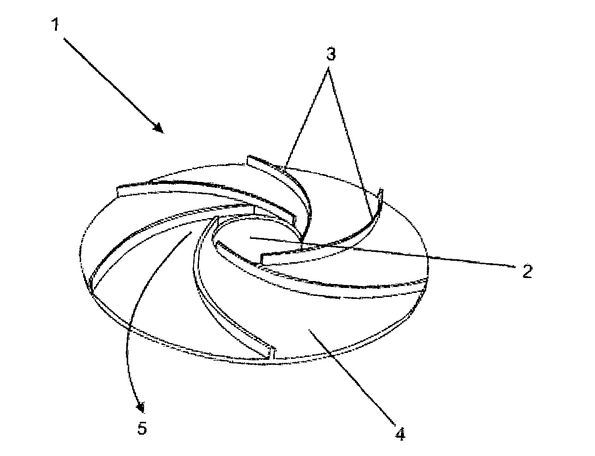
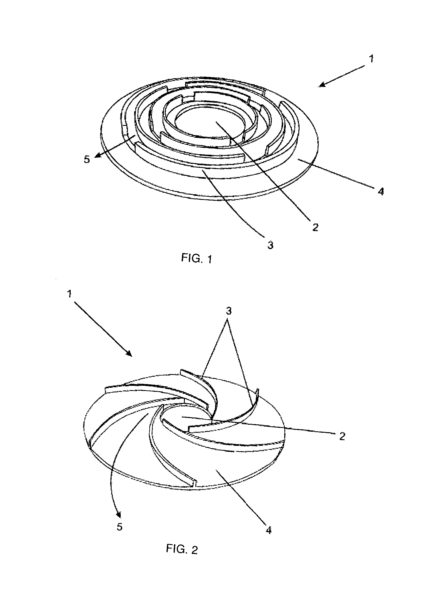
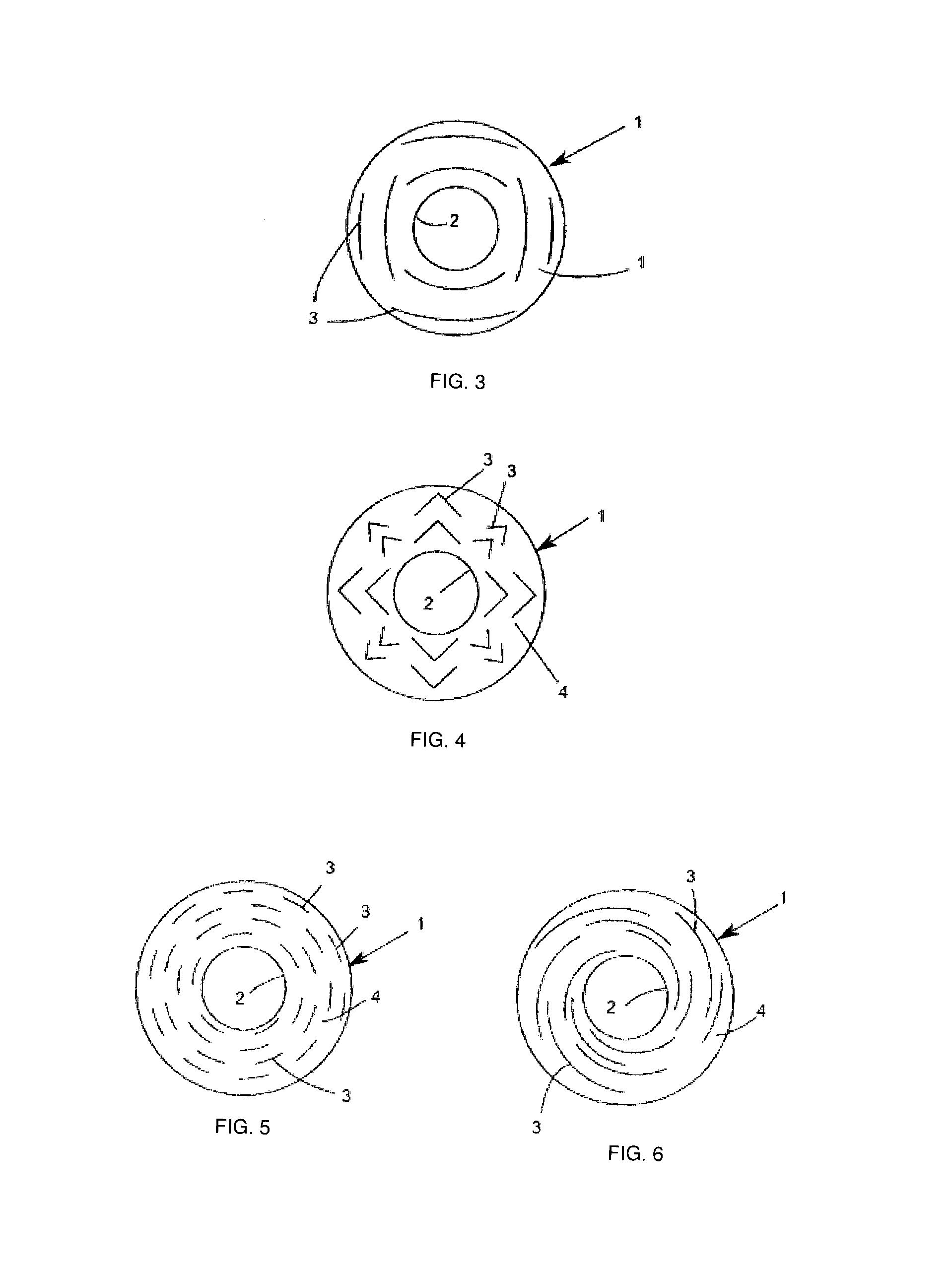
[0016]According to the above-mentioned schematic figures, the flame gas diffuser, in accordance with the present invention, comprises a cup 1 provided with a central opening 2 at which the cooking equipment burner is disposed, wherein on the surface 4 of said cup 1 barriers 3 are disposed, wherein said barriers are duly arranged and positioned in order to promote an extended passage pathways and channels for allowing the hot gas flow generated by the burner to pass.

[0017]As can be seen from the attached figures, it is possible to carry out a number of variations in the configurations concerning disposition and arrangement of said barriers 3. More particularly, FIGS. 1 to 4 illustrate mere examples of configurations, in which said barriers 3 are in a form capable of retaining or interrupting, at least partially, the continuous gas flow generated by the burner flame. In other words, said barriers 3 are intended to disturb or whirl the gas flow beneath the cooking utensil bottom, causi...


PUM


Abstract

The present invention generally refers to a flame gas burner diffuser to be used in stove-type cooking equipments, more preferably in household stoves, comprising technical and functional features capable of improving the efficiency of exchanging heat with the bottom of cooking utensils. More particularly, said diffuser, according to the present invention, comprises a cup (1) provided with a surface (4) comprising an opening (2) at which a cooking equipment is accommodated, wherein over said surface (4) there is a series of barriers (3) duly arranged and positioned so as to form passage pathways and/or extended channels for allowing the hot gas flow generated by the burner flame to pass.

Description

FIELD OF THE INVENTION[0001]The present invention generally refers to a flame gas burner diffuser used in cooking equipments, more preferably in household stoves, comprising technical and functional features capable of improving the efficiency of burners. More particularly, said diffuser, according to the present invention, comprises a structure provided with passages or channels formed on the surface over which a cooking utensil bottom of the cooking equipment rests, thereby increasing heat transfer levels.BACKGROUND OF THE INVENTION[0002]Stoves and cooking equipments known in the art usually comprise a series of burners upon which cooking utensils are disposed, wherein a configuration of said burners is intended to produce a flame capable of heating the utensil bottom and, preferably, such heating must be as uniform as possible.[0003]Thus, in order to improve the state-of-the-art burners, one may note that cooking equipment manufacturers are trying to develop parts and fittings fo...

Claims


Application Information

Patent Timeline
IPC IPC(8): F24C15/10
CPCF24C15/107F24C3/082Y02B40/00F24C15/101
Inventor SILVA, MARCOS RAPHAEL DA
Owner WHIRPOOL SA
Why Eureka
Try Eureka