
Heat exchanger of plate fin and tube type

Active Publication Date: 2007-07-19
MITSUBISHI ELECTRIC CORP
View PDF10 Cites 22 Cited by
  • Summary
  • Abstract
  • Description
  • Claims
  • Application Information

AI Technical Summary

Benefits of technology

[0006] In view of the above conventional problems, it is therefore an object of the present invention to provide a plate fin and tube type heat exchanger capable of preventing the space between fins from being blocked by frost even under the operational conditions causing frost buildup, while maintaining adequate heat exchange efficiency and compact size.
[0009] According to the heat exchanger of the present invention, the cut-raised portions formed in the fin on the upstream side and / or downstream side of the second fluid can induce the segmentation or renewal of a temperature boundary layer. This allows the heat exchanger to have enhanced heat exchanger efficiency and reduced size.
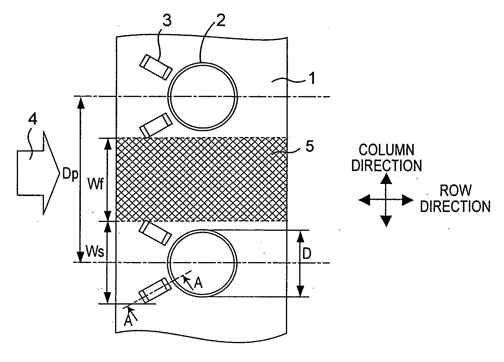
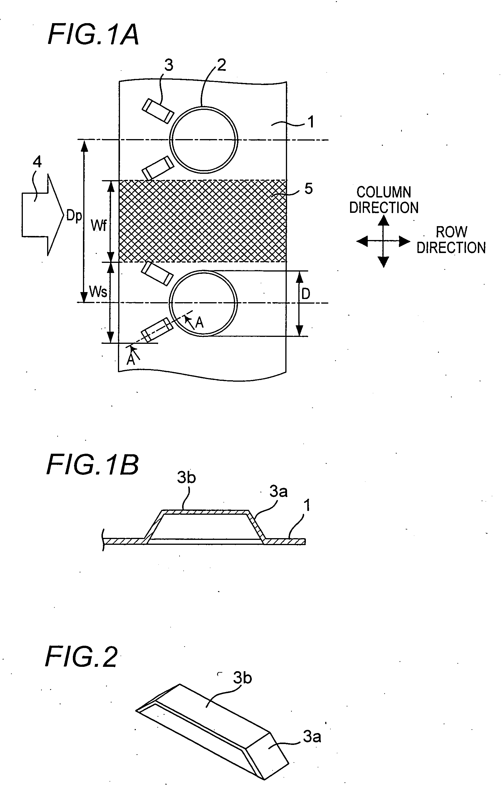
[0010] In addition, a zone formed with no cut-raised portion exists in the fin between the heat exchanger tubes aligned in the column direction. Thus, in case where the second fluid is air, and the heat exchanger is operated under the conditions causing frost buildup, even if the space between the adjacent fins is blocked in the vicinity of the cut-raised portions due to frost buildup, the air can flow through the zone with no cut-raised portion so as to suppress the reduction in air flow volume of the heat exchanger as a whole. Thus, even during the operation under the frost-buildup conditions, the heat exchange efficiency can be maintained in a high level. The cut-raised portion may be formed to extend obliquely relative to the column direction, so that the air can be directed toward a zone of the fin with no airflow on the downstream side of the heat exchanger tube to provide further enhanced heat exchange efficiency.
[0011] The cut-raised portion may also be formed in a bridge shape. In this case, the outer surface of a leg segment of the bridge connected to the body of the fin may be disposed in opposed relation to the heat exchanger tube to prevent the cut-raised portion from blocking the heat transfer from the heat exchanger tube. This allows heat from the heat exchanger tube to be effectively transferred to a region of the fin far from the heat exchanger tube.

Problems solved by technology

For example, in case where the plate fin and tube type heat exchanger is used in an outdoor unit of an air-conditioner, the heat exchanger is likely to be inevitably operated under the conditions causing frost buildup thereon.
In such a case, if the fin is formed with the cut-raised portion, frost will be liable to be created and grown at and around the cut-raised portion to block up the space between the adjacent fins.
Thus, in case where this type of heat exchanger is used under such conditions, for example, in an outdoor unit of an air-conditioner, the cut-raised portion cannot be formed in the fin, resulting in deteriorated heat exchange efficiency.
However, these measures involve problems, such as increase in installation area, material cost, fan-driving energy and noises.

Method used


Image

  • Heat exchanger of plate fin and tube type
  • Heat exchanger of plate fin and tube type
  • Heat exchanger of plate fin and tube type

Examples


first embodiment

[0036] As shown in FIGS. 1A and 1B, a heat exchanger according to a first embodiment of the present invention comprises a plurality of fins 1 (FIG. 1A shows only one of the fins) stacked while leaving a given space therebetween, and a plurality of heat exchanger tubes 2 penetrating the fins 1 in the stacking direction. Each of the fins 1 is formed with plural pairs of cut-raised portions 3 (or plurality of cut-raised portion pairs 3) each associated with the corresponding one of the heat exchanger tube 2. The heat exchanger is designed to perform a heat exchange between a first working fluid (e.g. heat transfer medium for air-conditioners) (not shown) allowed to flow inside the heat exchanger tubes, and a second working fluid 4 (e.g. air) allowed to flow outside the heat exchanger tubes, through the fin 1 and the heat exchanger tubes 2.

[0037] In the heat exchanger illustrated in FIGS. 1A and 1B, the plurality of heat exchanger tubes 2 are aligned in a given alignment pitch in one d...

second embodiment

[0064] With reference to FIG. 9, a second embodiment of the present invention will be described. A heat exchanger according to the second embodiment has a lot of common structures as those of the heat exchanger according to the first embodiment illustrated in FIGS. 1A to 7. For avoiding duplicate descriptions, the following description will be made by primarily focusing on different points from the first embodiment. In FIG. 9, a common element or component to that of the heat exchanger illustrated in FIG. 1A is defined by the same reference numeral.

[0065] As shown in FIG. 9, fundamentally as with the first embodiment, the heat exchanger according to the second embodiment comprises a plurality of fins 1, a plurality of heat exchanger tubes 2, a plurality of cut-raised portions 3, and a plurality of cut-raising inhibition zones 5 (FIG. 9 shows only one of the cut-raising inhibition zones 5). The heat exchanger also be designed to perform a heat exchange between a first working fluid ...

third embodiment

[0070] With reference to FIG. 10, a third embodiment of the present invention will be described. A heat exchanger according to the third embodiment has a lot of common structures as those of the heat exchanger according to the first embodiment illustrated in FIGS. 1A to 7. For avoiding duplicate descriptions, the following description will be made by primarily focusing on different points from the first embodiment. In FIG. 10, a common element or component to that of the heat exchanger illustrated in FIG. 1A is defined by the same reference numeral.

[0071] As shown in FIG. 10, fundamentally as with the first embodiment, the heat exchanger according to the third embodiment comprises a plurality of fins 1, a plurality of heat exchanger tubes 2, a plurality of cut-raised portions 3, and a plurality of cut-raising inhibition zones 5 (FIG. 10 shows only one of the cut-raising inhibition zones 5). The heat exchanger also be designed to perform a heat exchange between a first working fluid...


PUM


Abstract

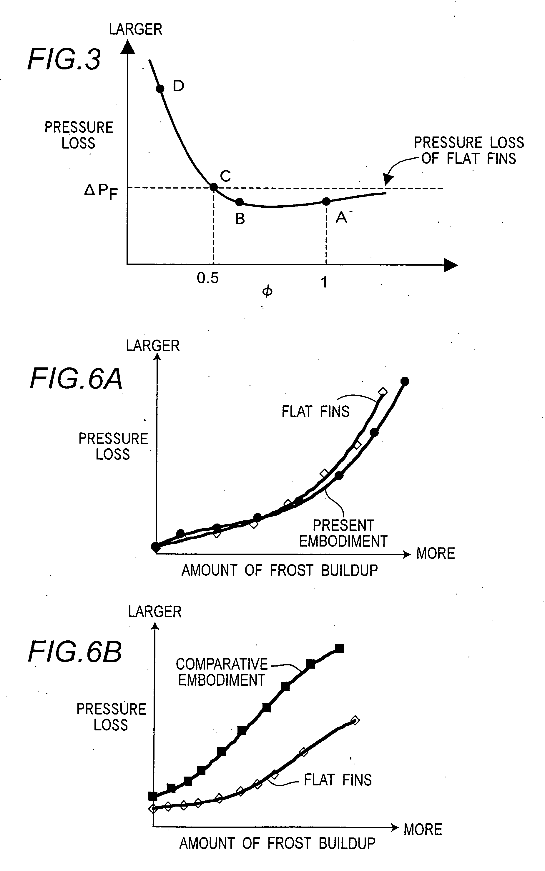
A heat exchanger including plate fins and, the tubes fins being stacked at respective intervals relative to one another, and heat exchanger tubes penetrating the fins in a fin-stacking direction. The heat exchanger exchanges heat between fluids flowing, respectively, inside and outside the heat exchanger tubes, through the heat exchanger tubes and the fins. Each of the fins includes cut-raised portions with a bridge shape having leg and beam segments. The cut-raised portions associated with each of the heat exchanger tubes are located substantially only in a region of the fin satisfyingWs=(1−φ)Dp+φDφ>0.5,where Ws is spread width of the cut-raised portions in a direction (column direction) extending along an end of the fin on the upstream side of the second fluid, and D is outer diameter of the heat exchanger tube. Dp is alignment pitch of the heat exchanger tubes in the column direction.

Description

TECHNICAL FIELD [0001] The present invention relates to a heat exchanger of plate fin and tube type in which a fin attached onto the outer periphery of a heat exchanger tube is formed with a cut-raised portion for providing enhanced heat exchange efficiency. BACKGROUND ART [0002] A plate fin and tube type heat exchanger which comprises a plurality of fins stacked while leaving a given space therebetween, and a plurality of heat exchanger tubes penetrating the fins in the stacking direction, is widely used, for example, as a condenser or evaporator for air-conditioners. For example, this type of heat exchanger is designed to perform a heat exchange between a first working fluid, such as water or chlorofluorocarbon, allowed to flow inside the heat exchanger tubes, and a second working fluid, such as air, allowed to flow outside the heat exchanger tubes or the spaces between the stacked fins, through the heat exchanger tubes and the fins. [0003] Generally, in the conventional heat exch...

Claims


Application Information

Patent Timeline
IPC IPC(8): F28F1/32
CPCF28F1/325F28F1/32
Inventor KAGA, KUNIHIKONAKADEGUCHI, SHINJIISHIBASHI, AKIRAWAKAMOTO, SHINICHIOHTE, TOSHINORIMURAKAMI, HIROKISAITO, TADASHI
Owner MITSUBISHI ELECTRIC CORP
Learn More