Miniature linear vibrotactile actuator

a technology of vibrotactile actuators and actuators, which is applied in the field ofhaptic interfaces, can solve the problems of actuator poses, difficult to produce a uniform magnetic field with great intensity, and the minimization of vibrotactile actuators, and achieve the effect of maximizing the intensity of electromagnetic for

Active Publication Date: 2014-11-27
SORBONNE UNIV +1
View PDF5 Cites 25 Cited by
  • Summary
  • Abstract
  • Description
  • Claims
  • Application Information

AI Technical Summary

Benefits of technology

[0020]That configuration of permanent magnets allows the production of a substantially uniform magnetic field with radial symmetry, whose magnetic field lines are concentrated at the location of the force generators and extend radially in the region thereof, which allows maximization of the intensity of the electromagnetic force induced by supplying the force generators with power.

Problems solved by technology

A major issue in the development of those applications is the miniaturization of the vibrotactile actuators.
The miniaturization of this type of actuator poses a given number of technical problems.
In particular, it is difficult to produce a uniform magnetic field which has great intensity without any device for channeling field lines.

Method used


Image

  • Miniature linear vibrotactile actuator
  • Miniature linear vibrotactile actuator
  • Miniature linear vibrotactile actuator

Examples


second embodiment

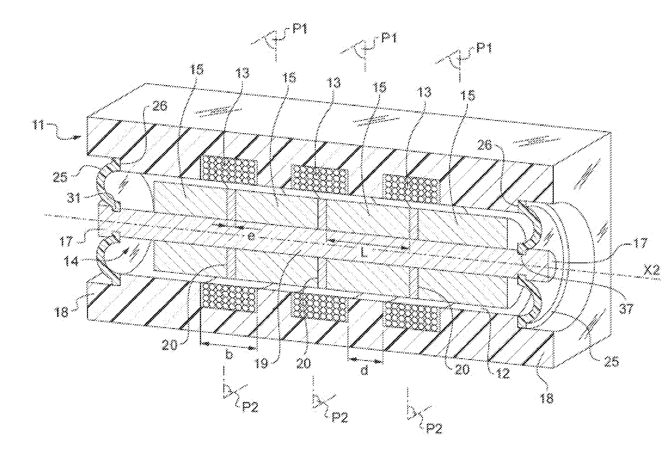
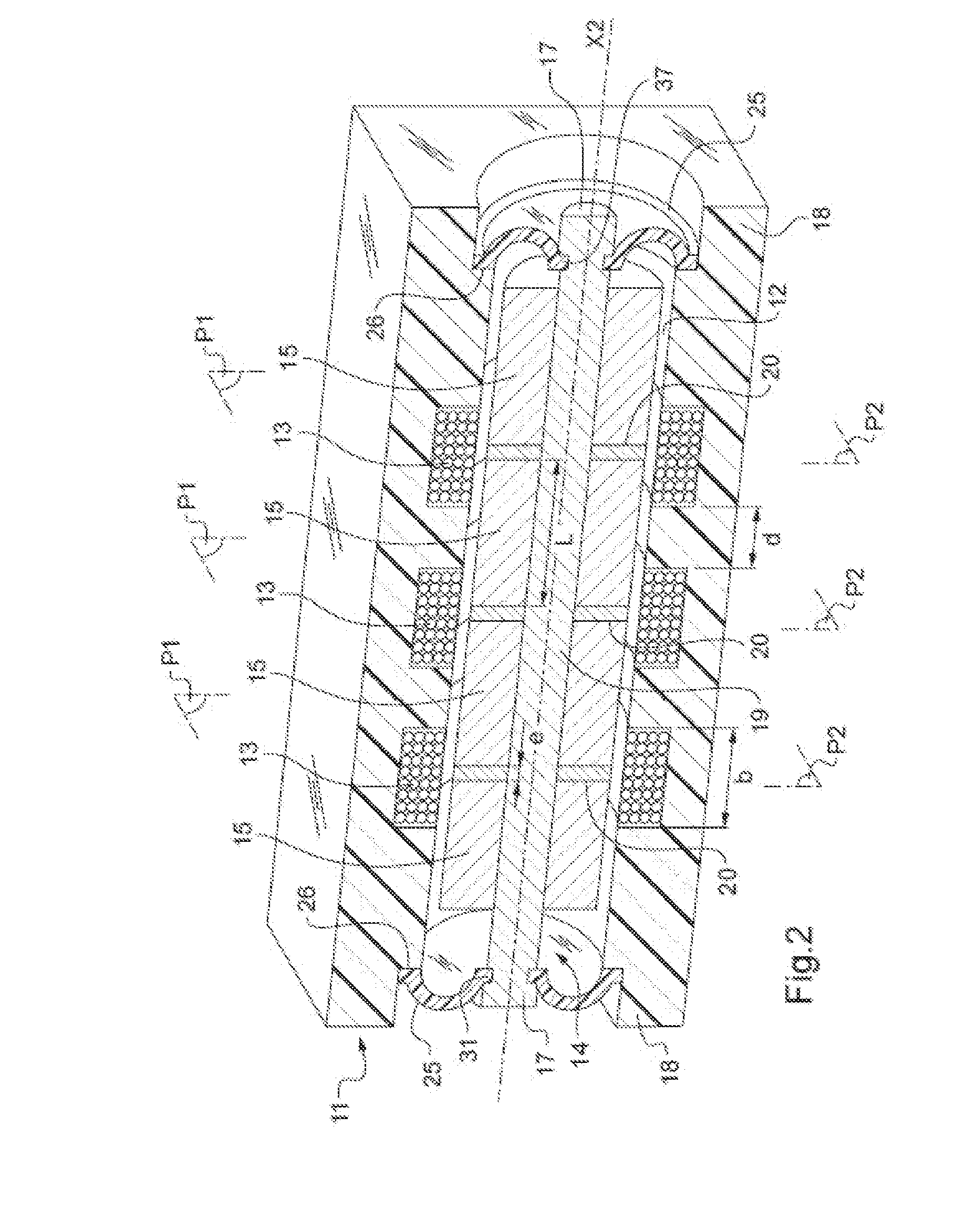
[0072]According to the invention, the actuator comprises coils and magnets which are of non-circular form, of rectangular cross-section, for example. Such an actuator is illustrated in FIGS. 7 and 8.

[0073]The actuator comprises a body 101 which defines a cavity 102 having a rectangular cross-section. The body 101 comprises six coils 103 of conductive wire of substantially parallelepipedal, planar form, which means here that the height h of a coil 103 is far smaller than its width H. The six coils 103 are distributed in two groups 107 of three aligned coils. In each group 107, the coils 103 are adjacent and arranged in the same plane P3 (illustrated in FIG. 8 with broken lines) so that the main axes X3 thereof are perpendicular to that plane P3. The groups 107 extend so as to define two opposing faces of the cavity 102.

[0074]The actuator further comprises a parallelepipedal movable fitting 104 which is inserted with little play inside the cavity 102 in order to be able to slide insid...

first embodiment

[0081]Although the actuator of the invention has been selectively illustrated so as to have four magnets and three coils, it is possible to use a different number of magnets and coils, the most advantageous configuration being to provide a number k of coils and a number k+1 of magnets, with k preferably being uneven.

[0082]Although the actuator of the invention according to the second embodiment has been selectively illustrated so as to have five magnets and six coils, it is possible to use a different number of magnets and coils, the most advantageous configuration being to provide a number k of magnets (k at least equal to three) and n of coils with n=2k−4.

[0083]Similarly, although specific forms of diaphragms have been set out, other forms could be advantageous. It is thereby possible to provide, for example, a diaphragm provided with concentric, circular folds. It is also possible to provide a diaphragm which is open-worked by means of openings, preferably of helical form, in or...


PUM

PropertyMeasurementUnit
frequenciesaaaaaaaaaa
lengthaaaaaaaaaa

Abstract

The invention relates to a miniature linear vibrotactile actuator comprising: a first element 14, 104 of generally cylindrical shape, comprising permanent magnets 15, 105 aligned so that two adjacent sides of two adjacent magnets 15, 105 have identical polarities; a second element 11, 101 defining a cylindrical cavity 12, 102 into which the first element 14, 104 is inserted with play so as to be able to slide therein in a sliding direction X2, the second element 11, 101 comprising coils 13, 103 of conductive wire having strands that extend perpendicularly to the sliding direction X2, in order to form magnetic force generators, and that are placed so as to be able to influence the first element 14, 104 electromagnetically; and means 25, 41, 125 for returning and guiding the first element 14, 104 toward an equilibrium position in the second element 11, 101, in which position a median plane P2 between two adjacent magnets substantially coincides with a median plane P1 of a facing force generator 111.

Description

[0001]The invention relates to a miniature linear vibrotactile actuator and a production method for such an actuator.BACKGROUND OF THE INVENTION[0002]Miniature vibrotactile actuators are used in a very large number of industrial applications, in particular in the field of haptic interfaces, which allow a human being to receive a piece of information transmitted by a machine by perceiving a tactile sensation.[0003]Among those haptic interfaces, force-feedback haptic interfaces which are used in particular in virtual reality devices provide a user with a tactile sensation corresponding to the one which would be felt in a simulated environment by the device. There are a large number of applications: video games, driving or flight simulation, simulation of surgery, etc.[0004]Other haptic interfaces are used only for transmitting a warning to a user, for example, in the case of a vibrating element of a mobile telephone or a tactile tablet, for example.[0005]A major issue in the developme...

Claims


Application Information

Patent Timeline
Patent Type & Authority Applications(United States)
IPC IPC(8): H02K33/00H02K15/14H02K15/06
CPCH02K33/00H02K15/14H02K15/06H02K33/16H02K2213/03Y10T29/49009H02K15/02H02K33/06H02K33/02
Inventor HAYWARD, VINCENTBERREZAG, AMIRDIETZ, GEORGE
Owner SORBONNE UNIV
Why Eureka
Try Eureka