Method and apparatus for generating electrical and mechanical energy
What is AI technical title?
AI technical title is built by Patsnap AI team. It summarizes the technical point description of the patent document.
a technology of electrical and mechanical energy and methods, applied in the direction of motor/generator/converter stopper, dynamo-electric converter control, shape/form/construction, etc., can solve the problems of no mechanism for controlling objects, energy loss, friction and other inefficiencies in the system, and achieve the effect of increasing enhancing the efficiency of mechanical embodiments
Inactive Publication Date: 2014-11-27
FARWELL LAWRENCE ASHLEY
View PDF8 Cites 11 Cited by
Summary
Abstract
Description
Claims
Application Information
AI Technical Summary
This helps you quickly interpret patents by identifying the three key elements:
Problems solved by technology
Method used
Benefits of technology
Benefits of technology
This patent describes a system for controlling the voltage, current, and magnetic field applied to an electromagnet in a device. This system uses a control module to switch the circuit when the device is in either a resistance or propulsion zone, reducing energy waste and increasing efficiency. The control module can also modulate the voltage and current to counteract the energy waste when the device is in the resistance zone. Additionally, the patent describes a mechanical embodiment that further reduces energy expenditure by using levers and a mechanical energy-storing mechanism. Combining these electronic and mechanical embodiments can further increase efficiency.
Problems solved by technology
They are inexhaustible in that they do not diminish when they are applied.
What is lost is the potential due to their relative position.
No mechanism for controlling the objects, harvesting the energy, and returning them to their initial position is 100% efficient, however.
Some energy is lost to friction and other inefficiencies in the system.
Thus, all symmetrical systems, when operated continually, result in a net loss of energy.
Symmetrical systems always result in a net loss of energy for two reasons: (1) the input of energy required to restore their components to their initial positions is equal to the energy gained when the components moved due to attraction and repulsion, and (2) some energy is lost due to friction and other inefficiencies in the system.
There is a loss of potential energy when the water flows downward through the turbines due to the force of gravity.
If the plant then pumped the water back up behind the dam to restore the potential energy based on the positioning of the water and the force of gravity, there would be a net loss of energy because the process would be less than 100% efficient.
Continuous expenditure of electrical energy is required to create and maintain this magnetic field.
Electromagnets consume power.
The difficulty, of course, is that without something added to the system this can only be done once.
Again, however, this can only be done once without something else added, because the initial potential energy in the system depends on the relative position of the magnets close to each other, and after the electricity is generated they are far apart.
Thus, even though the system will inevitably be hampered by friction, and the conversion of mechanical energy to electrical energy is less than 100% efficient, the system generates more energy than it consumes.
Method used
Image
Click on the blue label to locate the original text in one second.
Reading with bidirectional positioning of images and text.
Examples
Embodiment Construction
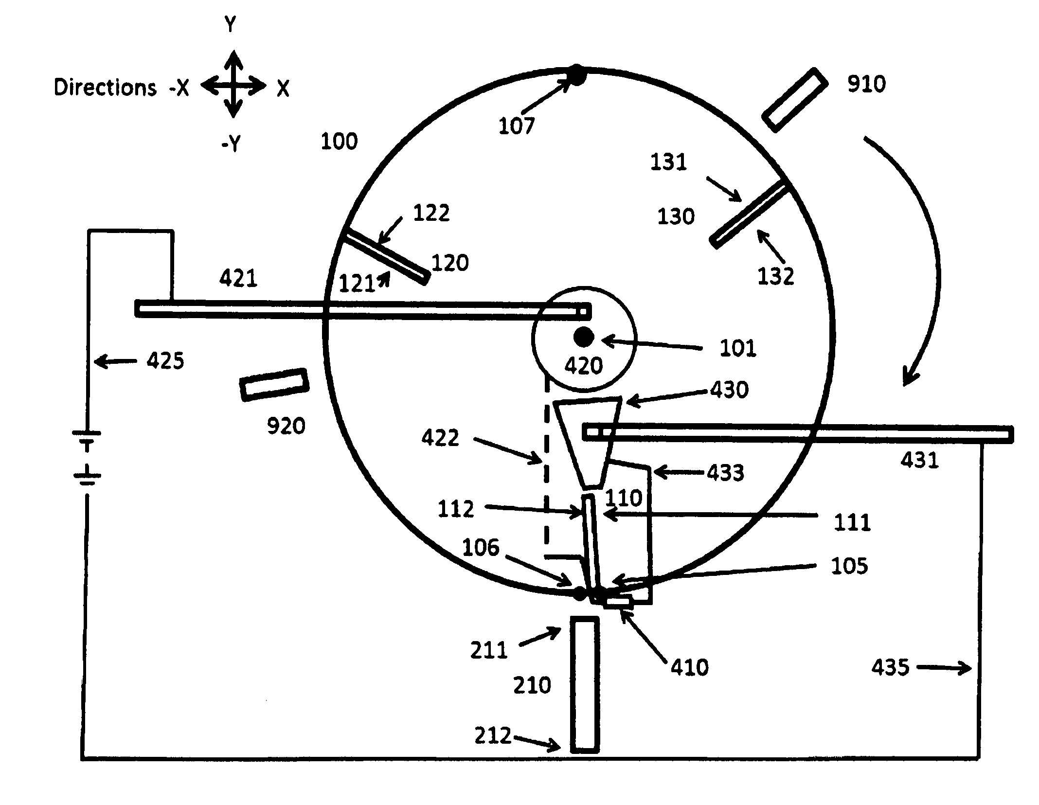
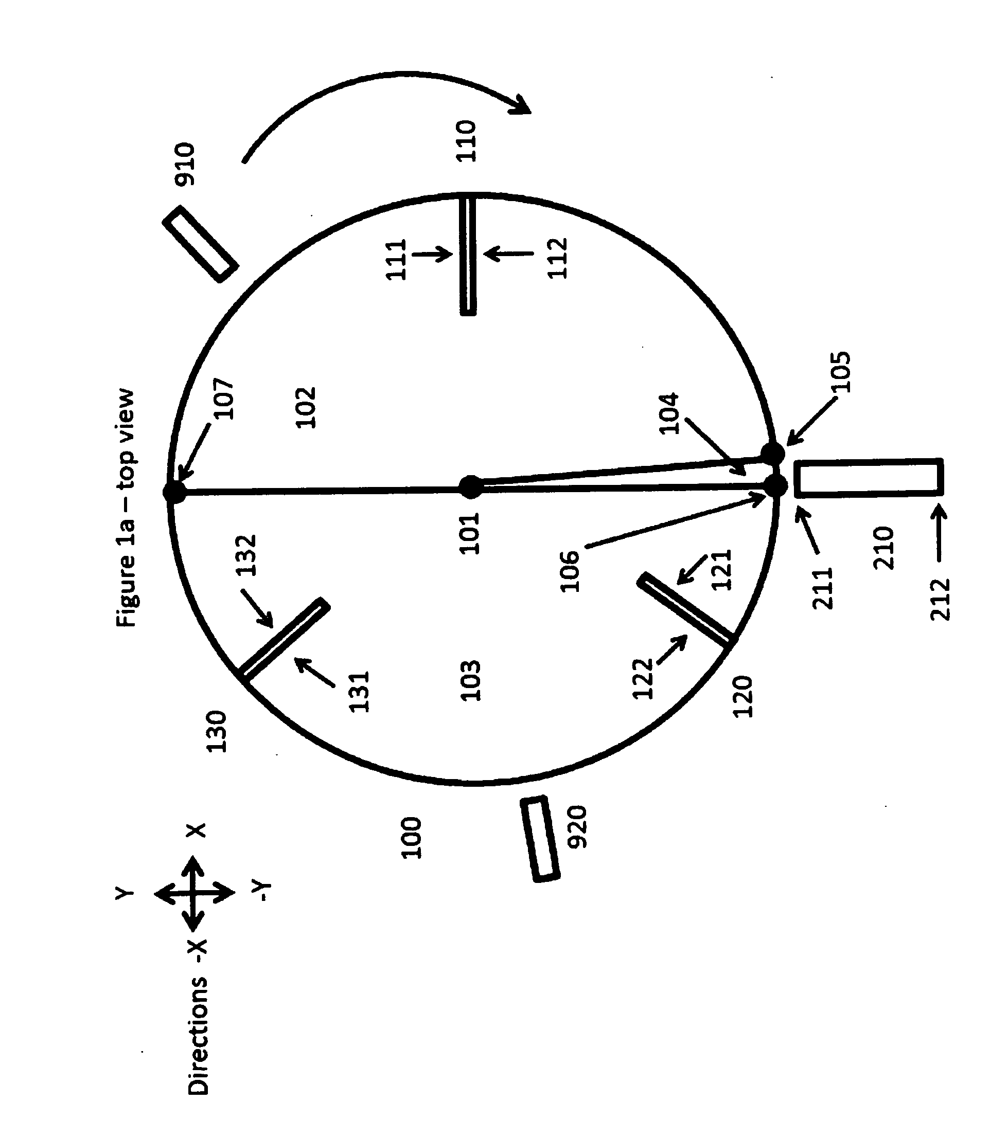
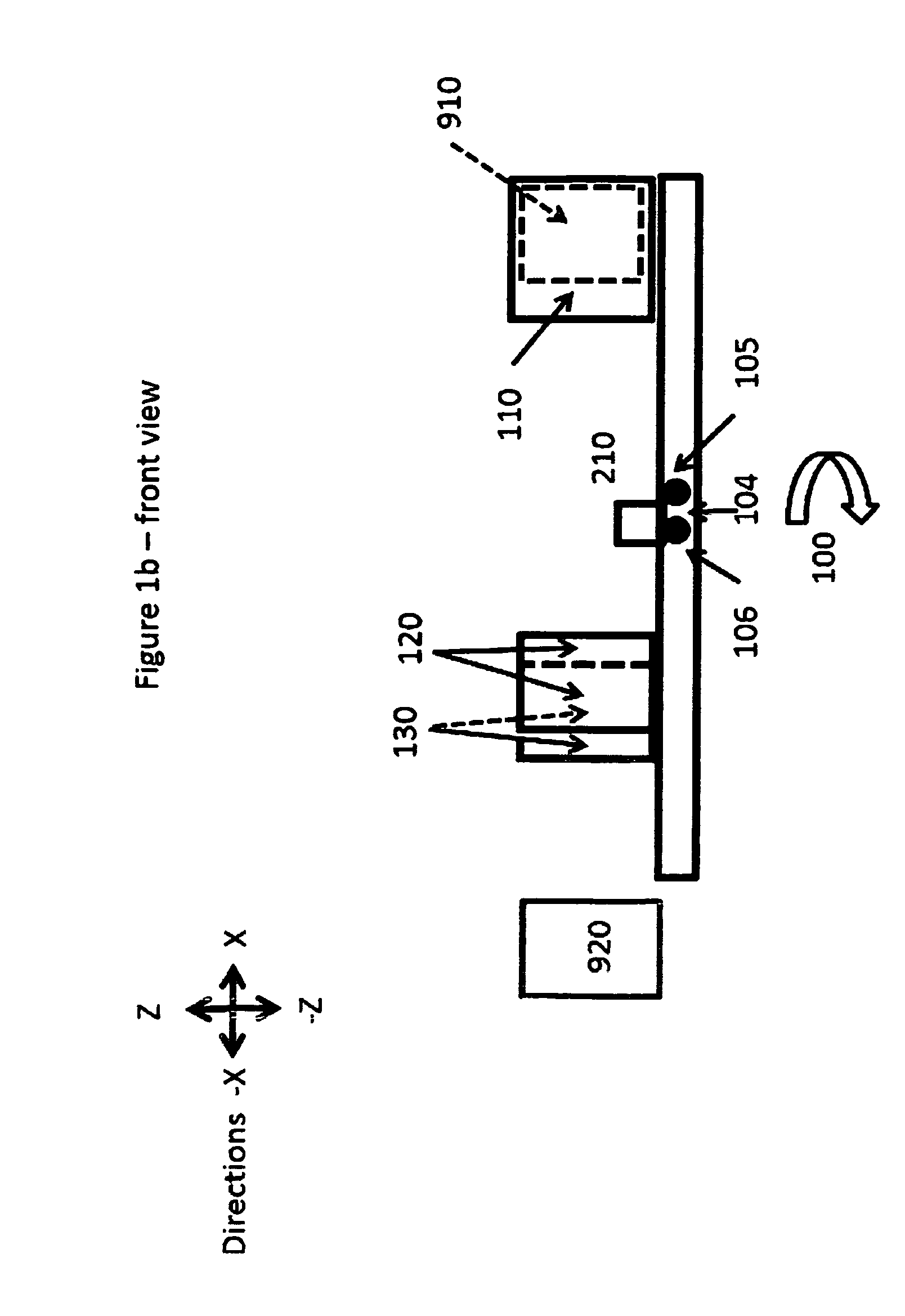
[0155]The invention is powered by the attraction and repulsion of permanent magnets.
[0156]In FIG. 1a, the driven magnet 110 is in the attraction zone, and the driven magnets 120 and 130 are in the repulsion zone. All driven magnets are in the propulsion zone.
[0157]Referring to driver magnet 210 and driven magnet 110, the forces between the magnets are as follows:[0158]Attraction between the north pole 211 of the driver magnet 210 and the south pole 112 of the driven magnet 110.[0159]Repulsion between the north pole 211 of the driver magnet 210 and the north pole 111 of the driven magnet 110.[0160]Attraction between the south pole 212 of the driver magnet 210 and the north pole 111 of the driven magnet 210.[0161]Repulsion between the south pole 212 of the driver magnet 210 and the south pole 112 of the driven magnet 110.
[0162]The attraction and repulsion involving the south pole 212 of the driver magnet 210 are extremely small, because the south pole 212 is far from the driven magnet...
PUM
Abstract
A method and apparatus for generating electrical energy comprises driven permanent magnets mounted tangentially on a freely rotating disk attached to a relatively stationary platform, and driver permanent magnets mounted on the platform radially to the disk. As the disk rotates, as a driven magnet approaches a driver magnet, their respective opposite poles attract, accelerating the disk. After the driven magnet passes the driver magnet, their like poles repel, also accelerating the disk. When the two permanent magnets are in close proximity, such that repulsion between like poles would decelerate the disk, an electromagnet is engaged between the two permanent to counteract this counterproductive force. One or more coils generate electricity through electromagnetic induction when the driven magnet passes them. A portion of this electricity powers the electromagnet, and the balance is the net energy generated.
Description
REFERENCES CITED[0001]U.S. PATENT DOCUMENTS3,890,548GrayJune 19753,913,004AlexanderOctober 19754,009,406InaribaFebruary 19774,151,431JohnsonApril 19794,179,633KellyDecember 19794,595,975GrayJune 19864,772,816SpenceSeptember 19884,823,038Mizutani et al.April 19895,363,858FarwellNovember 19945,406,956FarwellApril 19955,436,518KawaiJuly 19955,449,989Correa, Paulo, and AlexandraSeptember 19955,455,474FlynnOctober 19955,467,777FarwellNovember 19955,892,311HayasakaApril 19965,590,031Mead and NachamkinDecember 19965,625,241EwingApril 19975,694,419Rakestraw et al.December 19975,821,710Masuzawa et al.October 19985,973,436Satoh et al.May 20006,208,061AnMarch 20016,246,561FlynnJune 20016,362,718Patrick et al.March 20026,373,161KhalafApril 20026,392,370BediniMay 20026,462,451Kimura et al.October 20026,541,877Kim et al.April 20036,545,444BediniApril 20036,717,313BaeApril 20046,867,514FeceraMarch 20056,946,767ReardonSeptember 20057,151,332KundelDecember 20067,689,272FarwellMarch 2010U.K. PATENT D...
Claims
Application Information
Patent Timeline
Application Date:The date an application was filed.
Publication Date:The date a patent or application was officially published.
First Publication Date:The earliest publication date of a patent with the same application number.
Issue Date:Publication date of the patent grant document.
PCT Entry Date:The Entry date of PCT National Phase.
Estimated Expiry Date:The statutory expiry date of a patent right according to the Patent Law, and it is the longest term of protection that the patent right can achieve without the termination of the patent right due to other reasons(Term extension factor has been taken into account ).
Invalid Date:Actual expiry date is based on effective date or publication date of legal transaction data of invalid patent.
Patent Type & AuthorityApplications(United States)

