System for Power Balance Monitoring in Batteries

Active Publication Date: 2014-11-27
STRYTEN ENERGY LLC
View PDF3 Cites 8 Cited by
  • Summary
  • Abstract
  • Description
  • Claims
  • Application Information

AI Technical Summary

Problems solved by technology

For high power systems, the power control switches would be too large and expensive to place inside each module.
While the concepts outlined above generally outline the concepts of modular battery systems used in hi

Method used


Image

  • System for Power Balance Monitoring in Batteries
  • System for Power Balance Monitoring in Batteries
  • System for Power Balance Monitoring in Batteries

Examples


Embodiment Construction

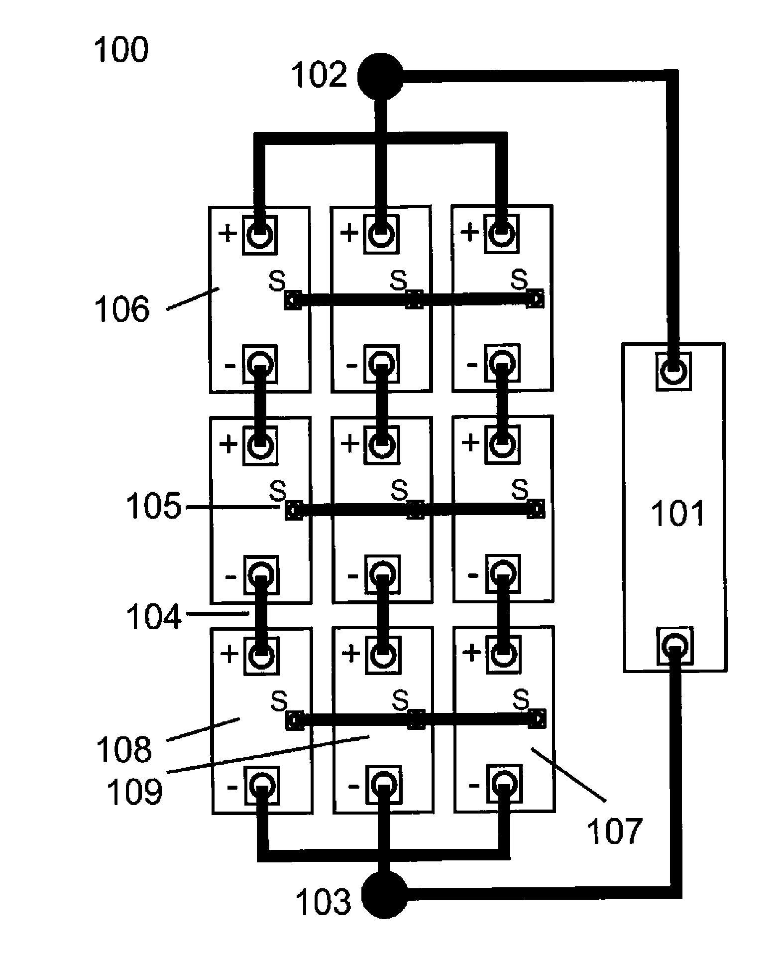
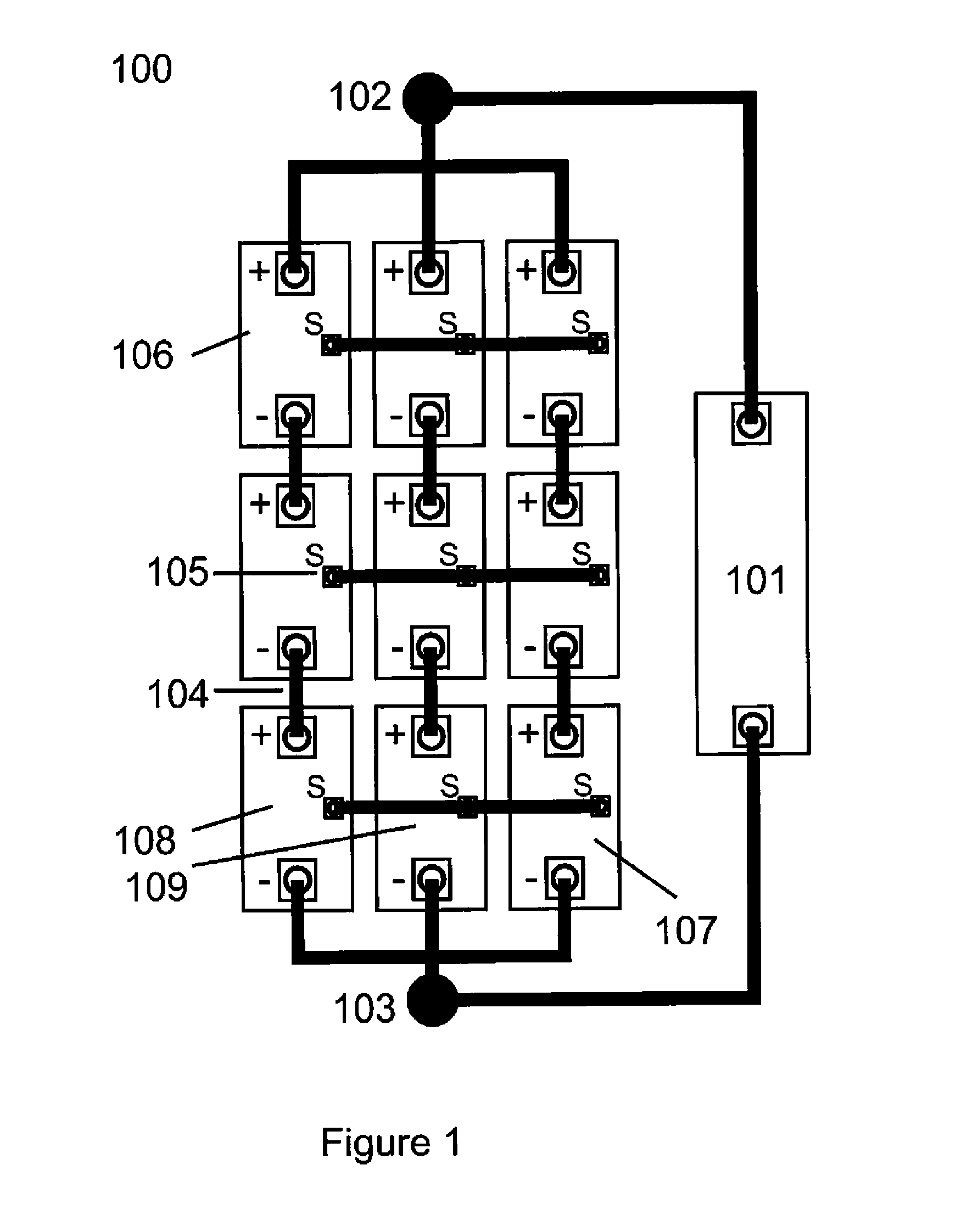
[0015]Referring to FIG. 3, the commonly practised method of connecting battery modules together is shown, This energy storage system (300) is composed of 3 modules in parallel, and then each parallel section is connected as a 3 series high stack of modules. This arrangement is commonly referred to as a 3S3P battery arrangement (3 Series, 3 Parallel). Each module (306) includes two terminals which are connected to other parallel modules using the connection wires (304). The most negative connection becomes the energy storage system negative terminal (303) and the most positive connection becomes the energy storage system positive terminal (302). The positive and negative terminals of the system arc then connected to a load (301) which may also include a charging source, electric motor controller, or any other source or consumer of electrical energy.

[0016]The commonly practised system of connecting batteries assumes that current flow through the system will be shared equally by each m...


PUM


Abstract

A system for power balance monitoring in an energy storage battery comprising a plurality of energy modules connected in a series-parallel configuration. The energy storage module comprises a plurality of cells. Each module is a three-terminal module. The three terminals comprise a positive output terminal and a negative output terminal for connecting the modules in a series string to a load and an energy sharing terminal for sharing energy between modules is other battery strings. A module power management sub-system comprising a current monitoring circuit is connected to each of the energy sharing terminals. Each module power management sub-system is in communication with a battery power management sub-system so that a weak module can be detected based on module current output. Advantageously, the module power management sub-system is not connected across the main power pathway of the module and so does not appreciably increase module impedance.

Description

TECHNICAL FIELD[0001]This invention relates to the field of high power rechargeable battery systems as they relate to both electric vehicle power and renewable home energy systems such as solar and wind power generation. Specifically the invention relates to a system for power balance monitoring in batteries within a high power rechargeable battery system.BACKGROUND ART[0002]High power battery systems are often composed of a multitude of individual electro-chemical cells that arc linked together in a combination of series and parallel connections to generate an overall battery system that has the appropriate voltage, current and energy storage characteristics for the application.[0003]Large battery systems are often broken down into smaller modules for ease of handling, monitoring and replacement. Each individual module will usually include electronics for maintaining the health, charge balance and monitoring of the cells within that module.[0004]For lower power systems, each module...

Claims


Application Information

Patent Timeline
IPC IPC(8): G01R31/36H02J7/00
CPCG01R31/3658H02J7/0014G01R31/3624H02J7/0016Y02T10/70H02J7/0047G01R31/396G01R31/3842H02J7/00
Inventor CARKNER, STEVELANOUE, ERIC
Owner STRYTEN ENERGY LLC
Why Eureka
Try Eureka