System and method for efficient surface measurement using a laser displacement sensor

Active Publication Date: 2014-11-27
COGNEX CORPORATION
View PDF3 Cites 50 Cited by
  • Summary
  • Abstract
  • Description
  • Claims
  • Application Information

AI Technical Summary

Benefits of technology

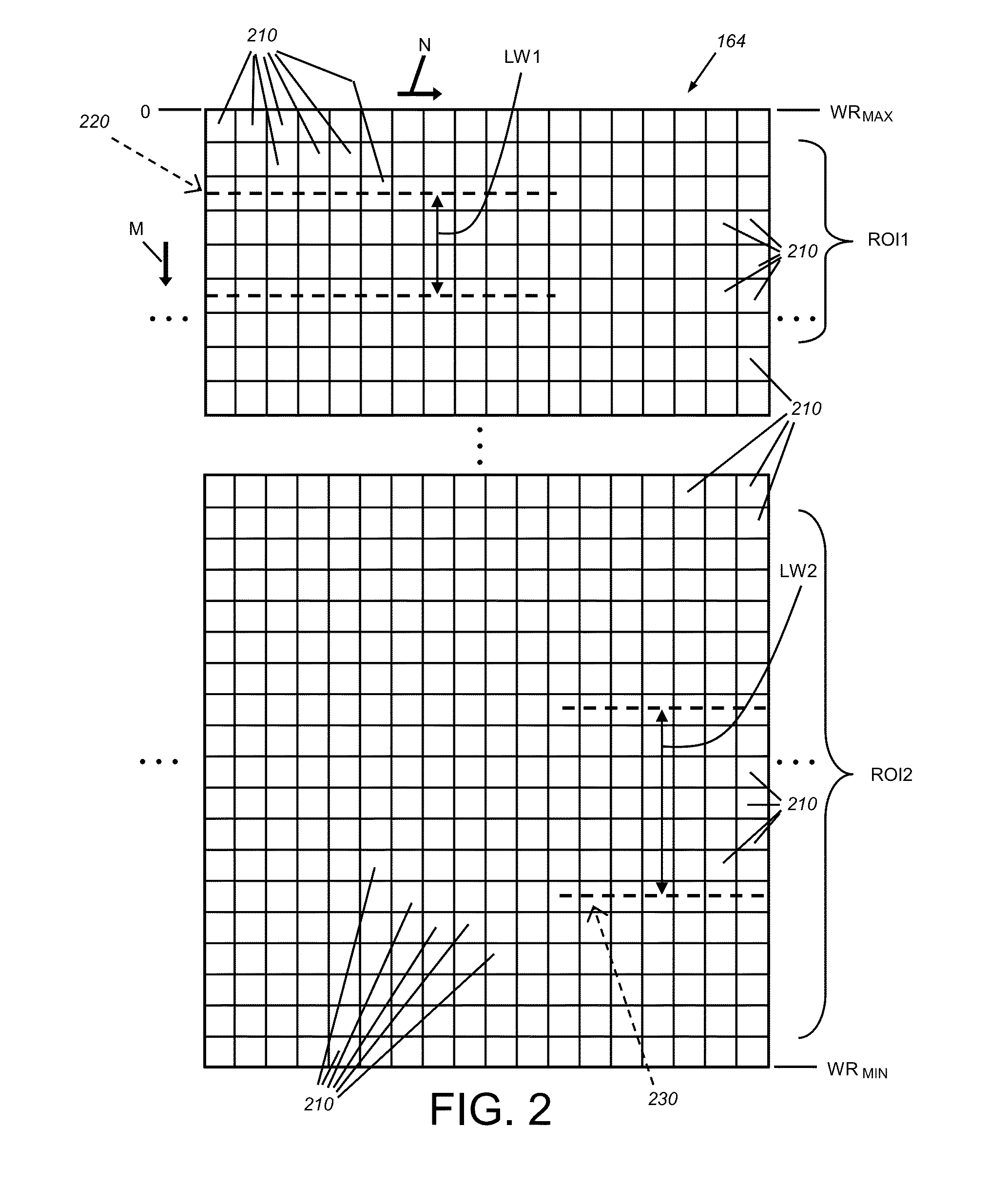
[0007]This invention overcomes disadvantages of the prior art, in illustrative embodiment by providing a laser displacement sensor system, and corresponding methods for scanning the height profile of an object surface, which increases scanning throughput, processing speed, efficiency and versatility of the system. In an illustrative embodiment, a displacement sensor projects a line on the object surface and receives light from the projected line at an imager in a manner defines a plurality of displacement values in a height direction. A vision system processor operates on rows of imager pixels to determine a laser line center, or more generally, the position of the laser line and/or specified portions of the line (e.g. the stop and start points of the line thickness) in columns of imager pixels in each of a plurality of regions of interest. Rows in areas outside the regions of interest are typically not acquired and/or processed so that the overall speed of acquiring and processing an image of the line is increased. Each region of interest defines a plurality of rows that correspond with expected locations of the projected line on the object surface. A height image is generated from the locations of the projected laser line in each scanned image as the object moves relative to the imager field of view

Problems solved by technology

The errors can comprise false height readings in the height image, such as encountered at a contrast change

Method used


Image

  • System and method for efficient surface measurement using a laser displacement sensor
  • System and method for efficient surface measurement using a laser displacement sensor
  • System and method for efficient surface measurement using a laser displacement sensor

Examples


Embodiment Construction

I. System Overview

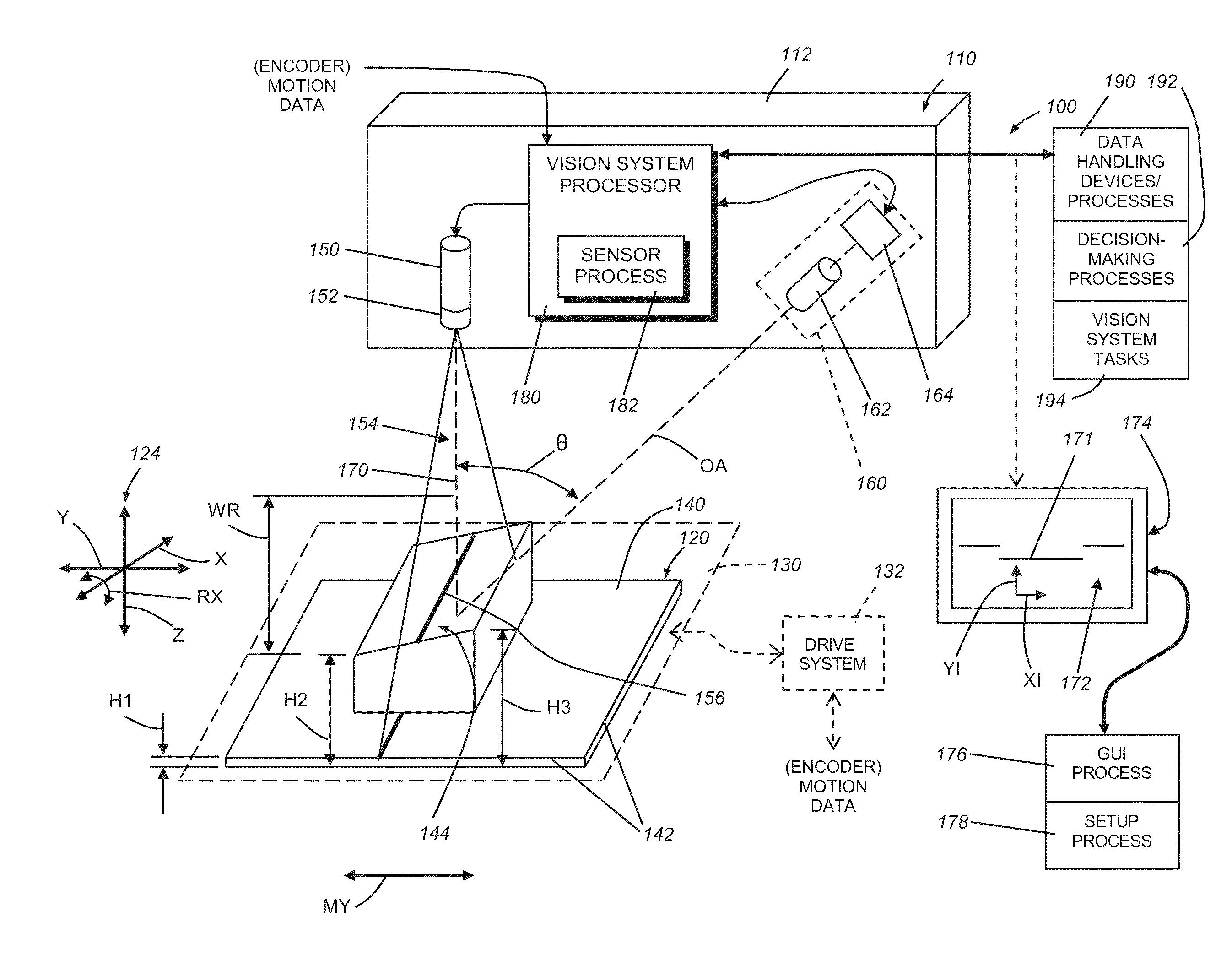
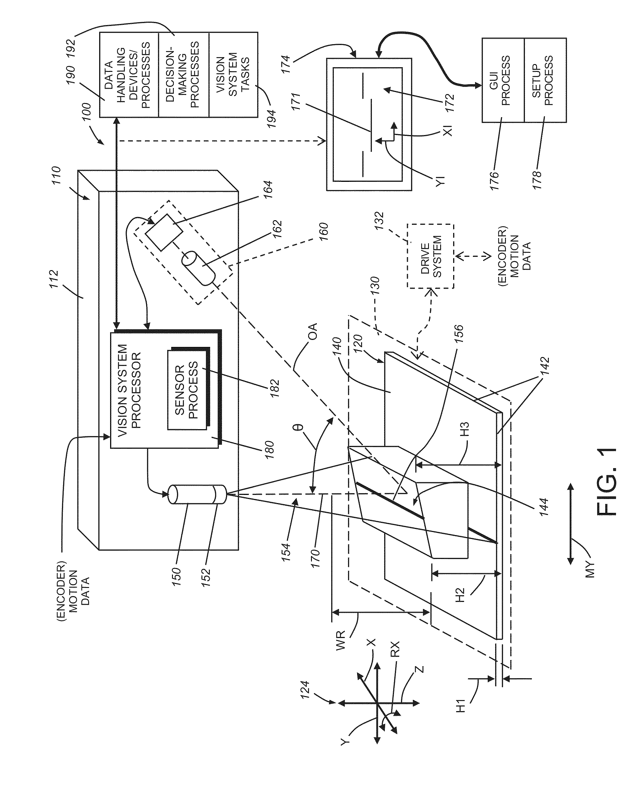
[0037]FIG. 1 shows a vision system arrangement 100 including a laser displacement sensor assembly 110 oriented to image an object 120 (also sometimes referred to as a “part”). The displacement sensor assembly (or, simply “displacement sensor”) can be contained in a single housing 112 that is mounted at an appropriate location with respect to the imaged scene. In alternate embodiments, the displacement sensor can comprise discrete, separated subcomponents. The object 120 and the displacement sensor 110 are in relative motion (double arrow My) with either the displacement sensor 110, the object 120, or both, moving (the scan motion direction) along at least one axis. The motion direction is often aligned with the depicted, relative (e.g. global) coordinate system 124 (in this example, the physical y-axis direction). In a typical arrangement, the object 120 is located on a moving surface 130 (shown in phantom), such as a conveyor belt or motion stage, which provides m...


PUM


Abstract

This invention provides a system for measuring displacement of an object surface having a displacement sensor that projects a line on the object surface and receives light from the projected line at an imager in a manner defines a plurality of displacement values in a height direction. A vision system processor operates on rows of imager pixels to determine a laser line center in columns of imager pixels in each of a plurality of regions of interest. Each region of interest defines a plurality of rows that correspond with expected locations of the projected line on the object surface. A GUI can be used to establish the regions. In further embodiments, the system generates grayscale images with the imager. These grayscale images can be compared to a generated height image to compensate for contrast-induced false height readings. Imager pixels can be compared to a reference voltage to locate the line.

Description

RELATED APPLICATIONS[0001]This application claims the benefit of U.S. Provisional Application Ser. No. 61 / 826,416, filed May 22, 2013, entitled SYSTEM AND METHOD FOR EFFICIENT SURFACE MEASUREMENT USING A LASER DISPLACEMENT SENSOR, the entire disclosure of which is herein incorporated by reference.FIELD OF THE INVENTION[0002]This invention relates to machine vision systems used in determining the displacement of an imaged object surface in three dimensions (3D).BACKGROUND OF THE INVENTION[0003]In manufacturing and assembly processes, it is often desirable to measure some or all of an object surface with a high degree of accuracy and generate a map of the overall displacement or “profile” (e.g. height in the physical z-coordinate direction) with respect to various locations on the object surface. This profile can be determined using a machine vision system (also termed herein “vision system”) in the form of a laser displacement sensor (also termed a laser beam “profiler”). A laser dis...

Claims


Application Information

Patent Timeline
IPC IPC(8): H04N7/18
CPCH04N7/18G01B11/026G01B11/2522G06V10/25G06V10/235G06T7/74G05B15/02G06T5/005G06T2200/24G06T2207/20072
Inventor WOLFF, ROBERT A.MOED, MICHAEL C.AKOPYAN, MIKHAILTREMBLAY, ROBERTFOSTER, WILLARDWALLACK, AARON S.
Owner COGNEX CORPORATION
Why Eureka
Try Eureka