Image processing apparatus, image processing method, and program

a technology of image processing and apparatus, applied in the field of image processing apparatus, can solve the problem of not being able to accurately determine whether or not a person has intruded into the intrusion prohibition region, and achieve the effect of enhancing the detection precision of objects and excellent effects

Active Publication Date: 2014-11-27
SONY SEMICON SOLUTIONS CORP
View PDF5 Cites 3 Cited by
  • Summary
  • Abstract
  • Description
  • Claims
  • Application Information

AI Technical Summary

Benefits of technology

[0006]Here, a case in which an object as a detection target, and another object are present in a range to be imaged of an apparatus for imaging a photographic subject (for example, imaging apparatus), for example, is assumed. For example, a case in which a fence (another object) which is provided at a boundary of a circumferential intrusion prohibition region, and a person (an object as a detection target) who is present in the vicinity of the intrusion prohibition region are present is assumed. In this case, for example, it is possible to detect the person who is present in the vicinity of the intrusion prohibition region, however, it is assumed that it is not easy to accurately determine whether or not a person has intruded into the intrusion prohibition region. Therefore, when it is possible to determine a positional relationship between the fence and a person in the depth direction of an image, for example, it is considered that whether or not a person has intruded into the intrusion prohibition region can be accurately determined.
[0007]It is desirable to enhance detection precision of an object.
[0008]According to an embodiment of the present technology, there are provided an image processing apparatus which includes a detection unit which detects an object which is included in an image; and a determination unit which determines a positional relationship between a detected object and a protective barrier region in a depth direction of the image based on a feature amount relating to at least one of the detected object and the protective barrier region when the detected object and the protective barrier region overlap with each other in the image, and an image processing method thereof, and a program which causes the method to be executed by a computer. In this manner, when a detected image and a protective barrier region overlap with each other in an image, it is possible to determine a positional relationship between the detected image and the protective barrier region in the depth direction of the image based on the feature amount relating to at least one of the detected object and the protective barrier region.
[0015]According to the present technology, it is possible to obtain an excellent effect of enhancing detection precision of an object.

Problems solved by technology

In this case, for example, it is possible to detect the person who is present in the vicinity of the intrusion prohibition region, however, it is assumed that it is not easy to accurately determine whether or not a person has intruded into the intrusion prohibition region.

Method used


Image

  • Image processing apparatus, image processing method, and program
  • Image processing apparatus, image processing method, and program
  • Image processing apparatus, image processing method, and program

Examples


second embodiment

2. Second Embodiment

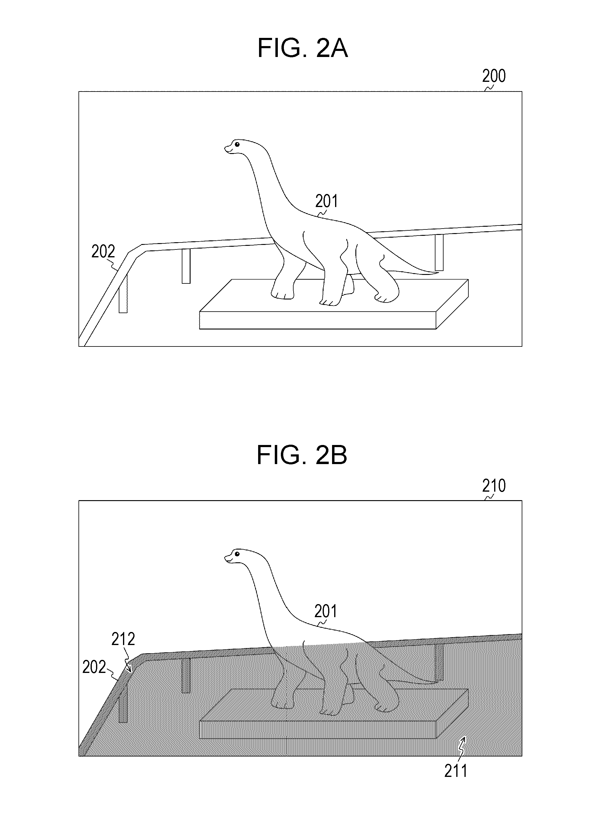
[0104]In the first embodiment of the present technology, the example in which the intrusion determination process of an object is performed using the protective barrier region information has been described. Here, for example, it is considered that it is also possible to perform an occlusion determination process (process of determining whether or not there is overlap in moving object) in a moving object detection process using the protective barrier region information.

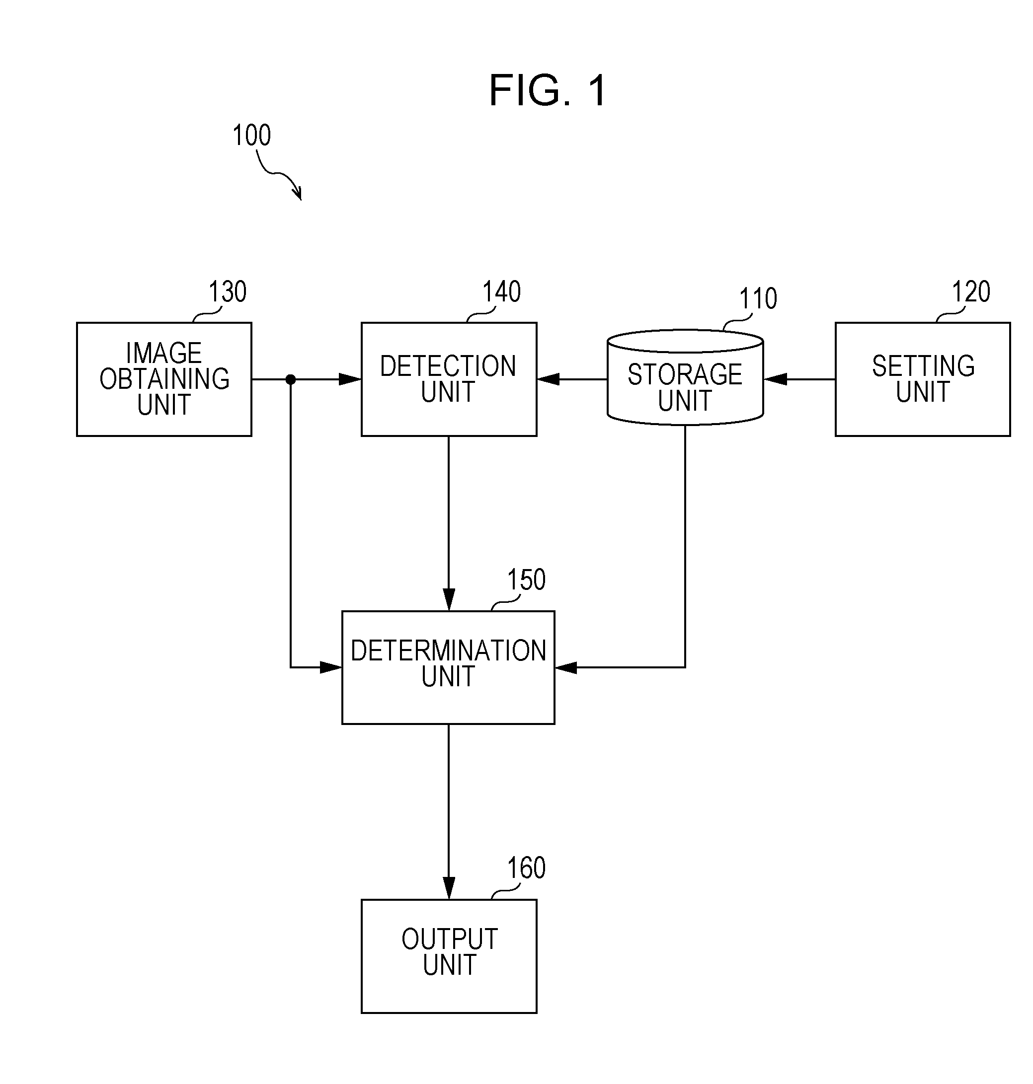
[0105]Therefore, in a second embodiment of the present technology, an example in which the occlusion determination process is performed using the protective barrier region information will be described. In addition, an image processing apparatus according to the second embodiment of the present technology is common to the image processing apparatus 100 (illustrated in FIG. 1) according to the first embodiment of the present technology. For this reason, common portions to those in the image processi...

third embodiment

3. Third Embodiment

[0151]In the first and second embodiments of the present technology, an example in which the image processing apparatus 100 is integrally configured has been described. However, it is also possible to apply the first and second embodiments of the present technology to an image processing system in which each function in the image processing apparatus 100 is executed by a plurality of devices.

[0152]Therefore, in a third embodiment of the present technology, an example of an image processing system which is configured of a plurality of devices will be described. In addition, each unit which configures the image processing system according to the third embodiment of the present technology corresponds to each unit which configures the image processing apparatus 100 illustrated in FIG. 1. For this reason, the fact will be indicated, and a part of descriptions of portions corresponding to the image processing apparatus 100 will be omitted.

Configuration Example of Image ...


PUM


Abstract

An image processing apparatus includes a detection unit which detects an object which is included in an image; and a determination unit which determines a positional relationship between a detected object and a protective barrier region in a depth direction of the image based on a feature amount relating to at least one of the detected object and the protective barrier region, when the detected object and the protective barrier region overlap with each other in the image.

Description

CROSS REFERENCE TO RELATED APPLICATIONS[0001]This application claims the benefit of Japanese Priority Patent Application JP 2013-110264 filed May 24, 2013, the entire contents of which are incorporated herein by reference.BACKGROUND[0002]The present technology relates to an image processing apparatus. Specifically, the present technology relates to an image processing apparatus which handles an image, an image processing method, and a program which causes a computer to execute the method.[0003]In the related art, an image processing apparatus such as an imaging apparatus which images a photographic subject such as a person, and generates an image (image data) has become widespread. In addition, a technology of recognizing a photographic subject which detects an object such as a person, or a moving object included in an image generated in this manner has been proposed.[0004]An image processing apparatus which detects a face of a person which is included in an image, using an image pr...

Claims


Application Information

Patent Timeline
Patent Type & Authority Applications(United States)
IPC IPC(8): G06K9/00G06T7/00
CPCG06K9/00771G06K9/00362G06T7/0042G06T2207/30196G06T2207/30232G06T7/73G06V20/52
Inventor SANO, HIRONAGA
Owner SONY SEMICON SOLUTIONS CORP
Why Eureka
Try Eureka