System And Method Of Material Handling Using One Imaging Device On The Receiving Vehicle To Control The Material Distribution Into The Storage Portion Of The Receiving Vehicle

a technology of imaging device and receiving vehicle, which is applied in the field of method and stereo vision system, can solve the problems of affecting affecting the accuracy of agricultural materials, etc., and achieves the effect of facilitating the transfer of agricultural materials

Active Publication Date: 2014-11-27
DEERE & CO
View PDF14 Cites 37 Cited by
  • Summary
  • Abstract
  • Description
  • Claims
  • Application Information

AI Technical Summary

Benefits of technology

[0005]The system and method facilitates the transfer of agricultural material from a transferring vehicle (e.g., harvesting vehicle) to a receiving vehicle (e.g., grain cart). The system and method comprises a receiving vehicle, which has a propelled portion for propelling the receiving vehicle and a storage portion for storing agricultural material and a transferring vehicle for transferring harvested agricultural material into the storage portion of the receiving vehicle.

Problems solved by technology

However, such prior art systems are susceptible to misalignment of the proper spacing because of errors or discontinuities in the estimated position of the GPS receivers.
For example, one or more of the GPS receivers may misestimate its position because of electromagnetic interference, multipath propagation of the received satellite signals, intermittent reception of the satellite signals or low received signal strength of the satellite signals, among other things.
If the vehicles use cameras or other imaging devices in an outdoor work area, such as an agricultural field, the imaging devices may be subject to transitory sunlight, shading, dust, reflections or other lighting conditions that can temporarily disrupt proper operation of the imaging devices; hence, potentially produce errors in estimated ranges to objects observed by the imaging devices.

Method used


Image

  • System And Method Of Material Handling Using One Imaging Device On The Receiving Vehicle To Control The Material Distribution Into The Storage Portion Of The Receiving Vehicle
  • System And Method Of Material Handling Using One Imaging Device On The Receiving Vehicle To Control The Material Distribution Into The Storage Portion Of The Receiving Vehicle
  • System And Method Of Material Handling Using One Imaging Device On The Receiving Vehicle To Control The Material Distribution Into The Storage Portion Of The Receiving Vehicle

Examples


Embodiment Construction

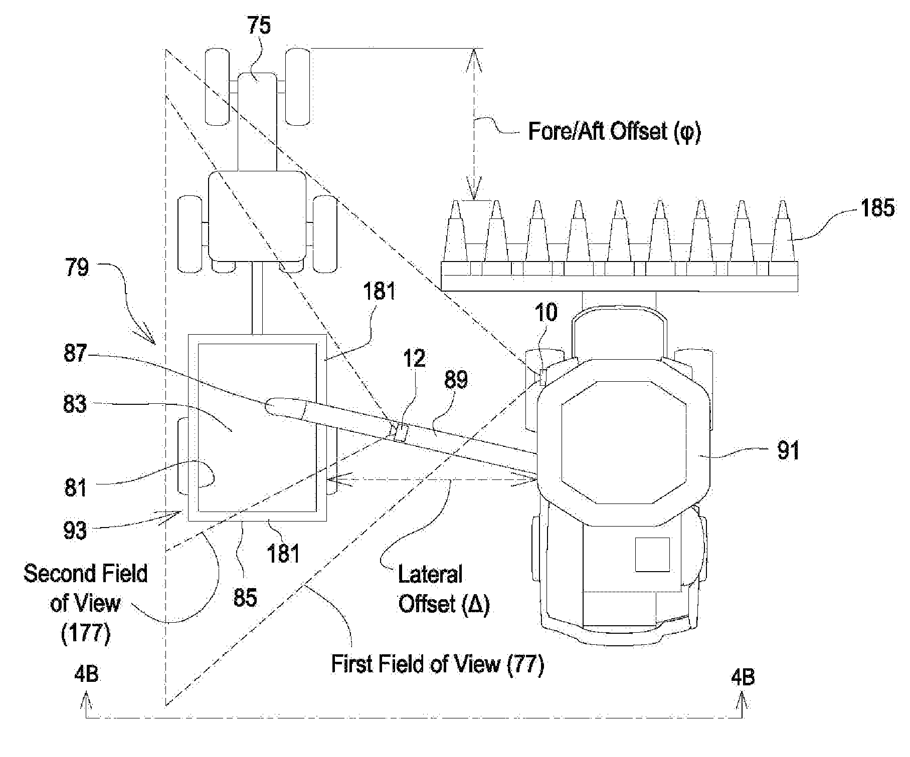
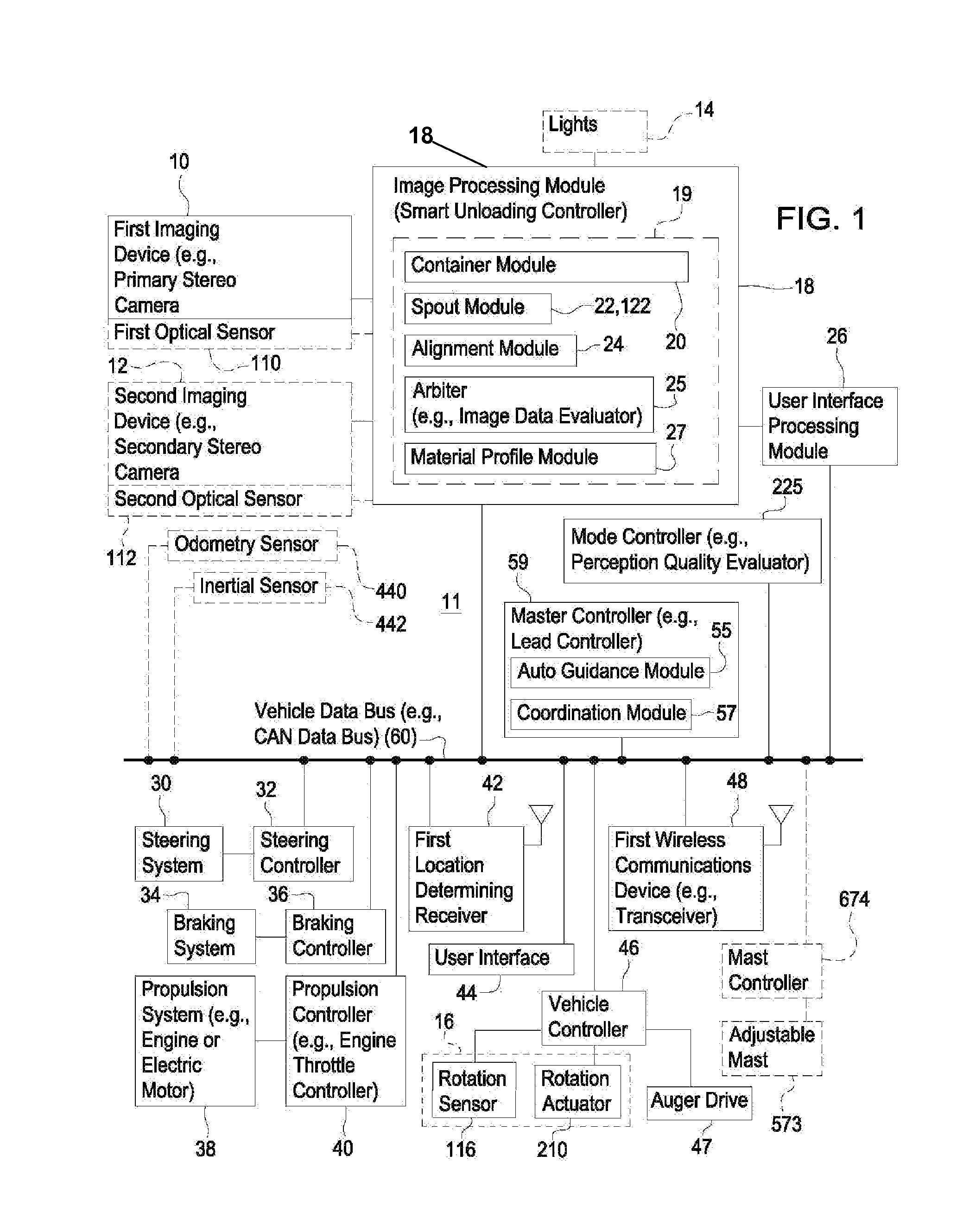
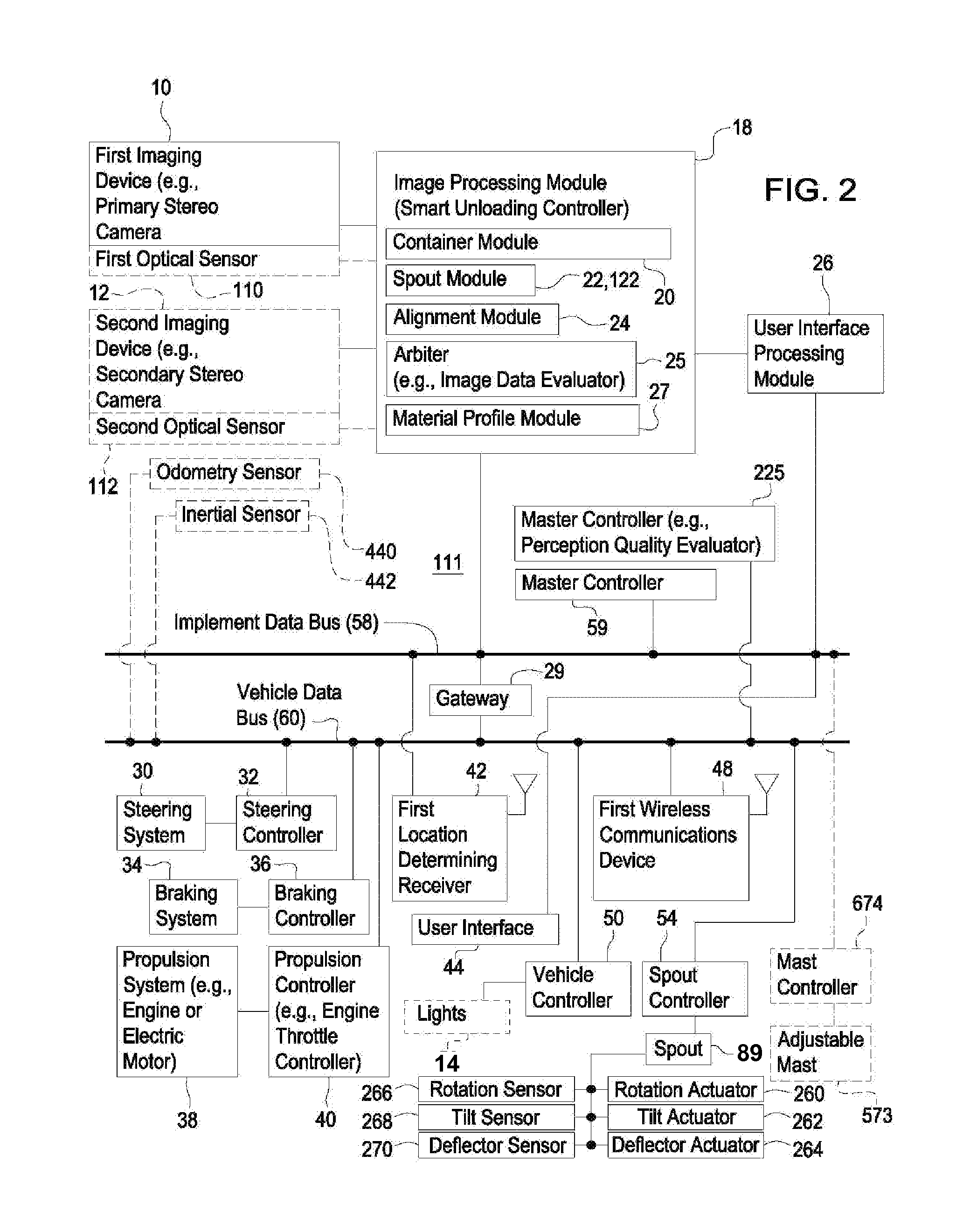
[0031]In accordance with one embodiment of the present invention that requires imaging devices only on the receiving vehicle 79, FIGS. 3A, 5A and 5B show a machine vision augmented guidance system 311 for a receiving vehicle 79 for managing the unloading of agricultural material (e.g., grain) from the transferring vehicle 91 (e.g., combine) to a receiving vehicle 79 (e.g., grain cart or wagon). FIG. 5A illustrates a top view of an exemplary transferring vehicle 91 and a receiving vehicle 79 configuration. FIG. 5B illustrates a side view of an exemplary transferring vehicle 91 and a receiving vehicle 79 configuration of FIG. 5A. For example, a stereo imaging system augments satellite navigation receivers or location-determining receivers 142 for guidance of receiving vehicle 79. The imaging device 10 has a field of view 277, indicated by the dashed lines. The boundaries of the field of view 277 are merely shown for illustrative purposes and will vary in actual practice. The system 31...


PUM


Abstract

A single imaging device collects image data of a storage portion. A container module identifies a container perimeter of the storage portion in at least one of the collected image data. A spout module is adapted to identify a spout of the transferring vehicle in the collected image data. An arbiter determines whether to use the image data based on an evaluation of the intensity of pixel data or ambient light conditions. An alignment module is adapted to determine the relative position of the spout and the container perimeter and to generate command data to the propelled portion to steer the storage portion in cooperative alignment such that the spout is aligned within a central or target zone of the container perimeter.

Description

CROSS-REFERENCE TO RELATED APPLICATIONS[0001]This application is a Continuation In Part application of PCT International Application PCT / US2013 / 025572, filed Feb. 11, 2013, titled SYSTEM AND METHOD OF MATERIAL HANDLING USING ONE IMAGING DEVICE ON THE RECEIVING VEHICLE TO CONTROL THE MATERIAL DISTRIBUTION INTO THE STORAGE PORTION OF THE RECEIVING VEHICLE, which claims the priority of U.S. Provisional Application 61 / 597,346, filed Feb. 10, 2012, and U.S. Provisional Application 61 / 597,374, filed Feb. 10, 2012, and U.S. Provisional Application 61 / 597,380, filed Feb. 10, 2012, all are incorporated by reference herein.JOINT RESEARCH AGREEMENT[0002]This application resulted from work performed under or related to a joint research agreement between Carnegie Mellon University and Deere & Company, entitled “Development Agreement between Deere & Company and Carnegie Mellon University,” dated Jan. 1, 2008 and as such is entitled to the benefits available under 35 U.S.C. §103(c).FIELD OF THE IN...

Claims


Application Information

Patent Timeline
Patent Type & Authority Applications(United States)
IPC IPC(8): A01D43/08
CPCA01D43/087G06T7/70G06T7/593G06T7/13G06T7/62G05D1/0251G05D1/0293G05D2201/0201H04N13/128B65G67/22B60R11/04B65G67/24A01D75/00G16Z99/00A01D43/07A01B69/00A01D43/06G06F7/70B65B1/48G05D1/02G05D1/021A01D41/1275B65F9/00B65F2210/182H04N7/181H04N7/183G06T2207/10021G06T2207/10028G06T2207/20061G06T2207/30252G06F18/22B60P1/42H04N7/18B62D6/001G05D1/0246G06T7/20G06T2207/20228
Inventor BONEFAS, ZACHARY T.
Owner DEERE & CO
Why Eureka
Try Eureka