Drive device, electronic component carrying device, electronic component inspection device, robot hand, and robot
a technology of electronic components and driving devices, which is applied in the direction of multiple dynamo-motor starters, dynamo-electric converter control, instruments, etc., can solve the problems of difficult to further reduce the size, weight and cost of the driving device, and the positioning accuracy of the arm portions can be improved, and the movement of the moving parts can be fine, the effect of easy misalignmen
- Summary
- Abstract
- Description
- Claims
- Application Information
AI Technical Summary
Benefits of technology
Problems solved by technology
Method used
Image
Examples
first embodiment
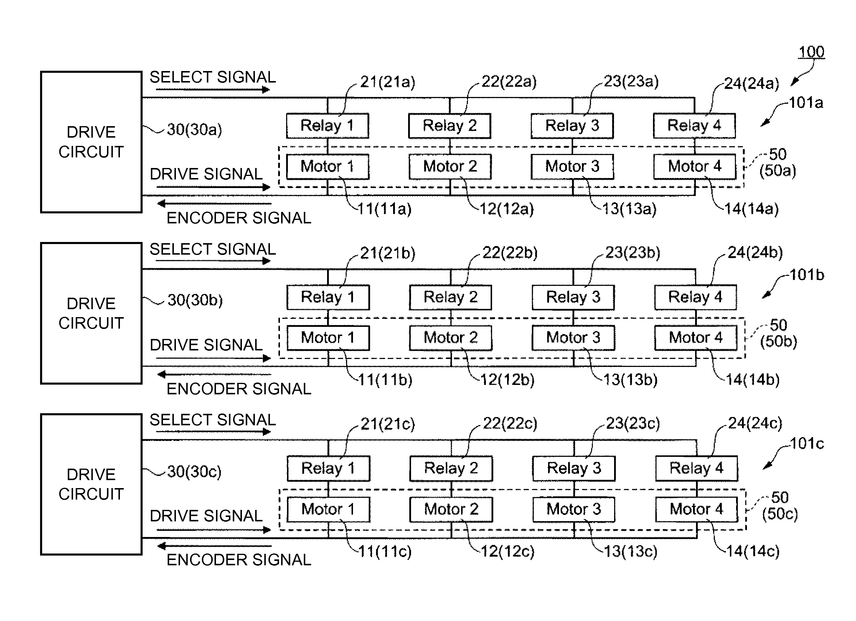
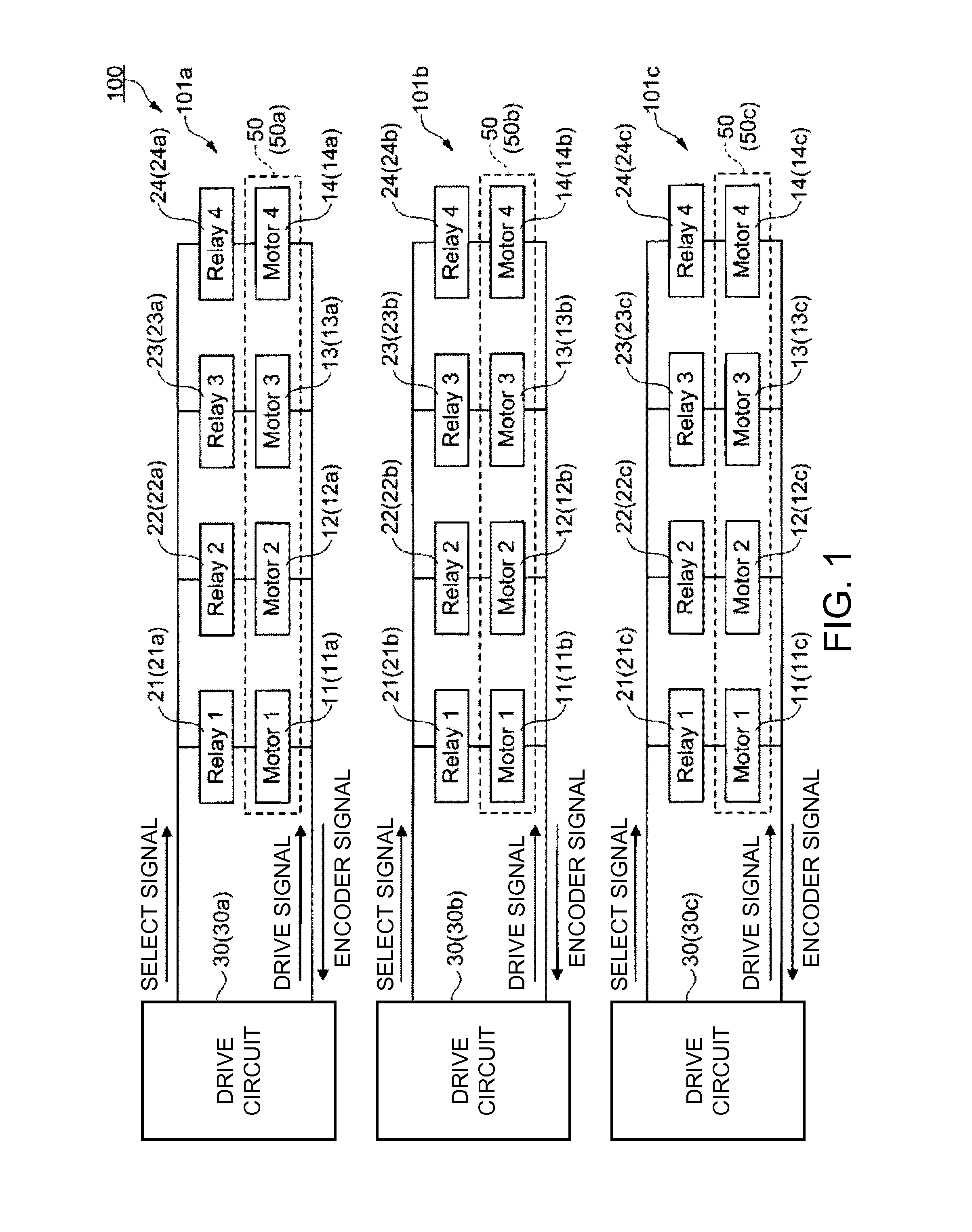
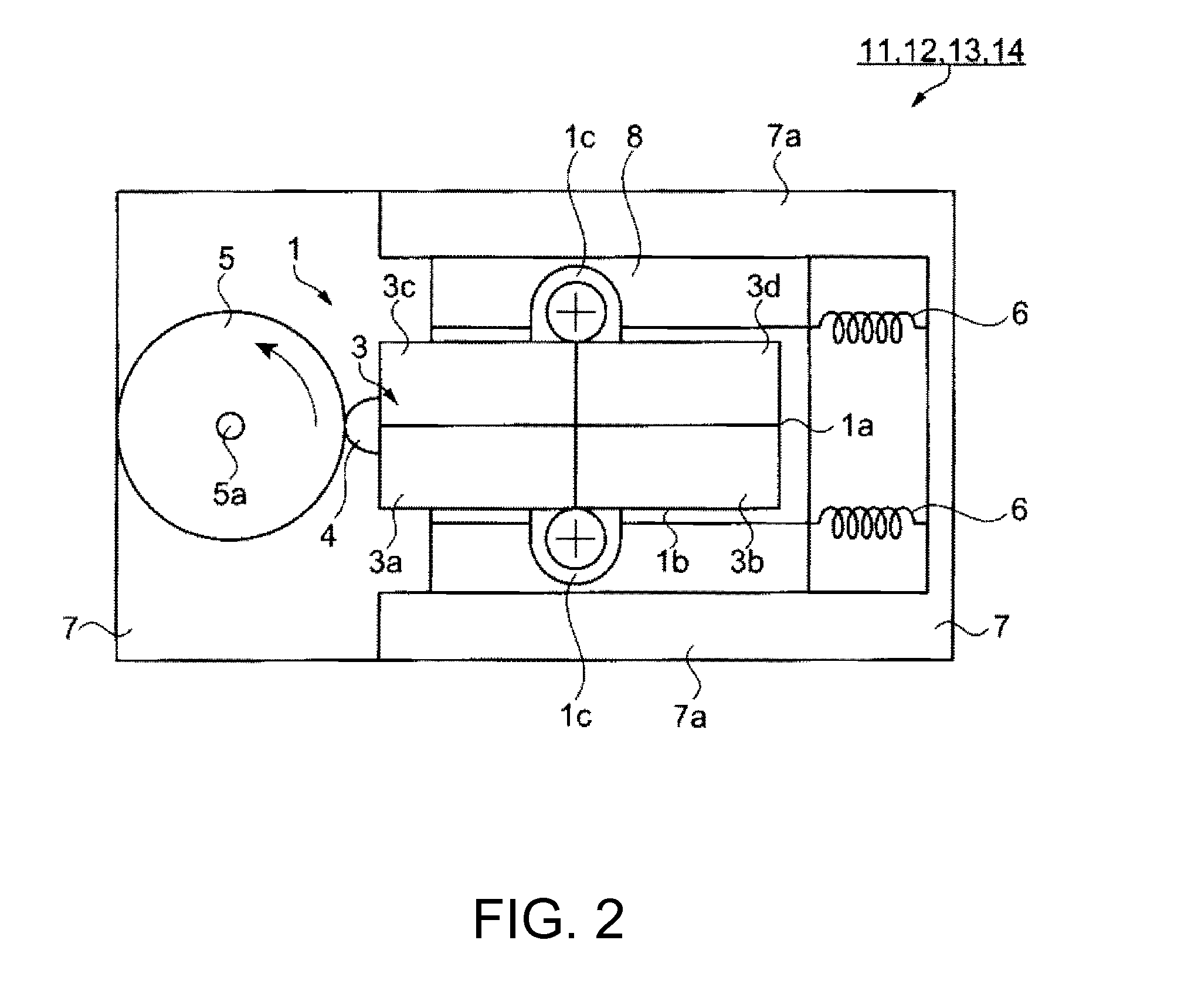
[0083]FIG. 1 is a block diagram showing the schematic configuration of a drive device according to a first embodiment. FIG. 2 is a schematic view showing the configuration of a piezoelectric motor used in the drive device according to the first embodiment. FIG. 3 is a block diagram showing the configuration of the drive device according to the first embodiment. FIG. 4 is a block diagram showing the configuration of a drive circuit according to the first embodiment. FIGS. 5A to 5E illustrate a drive control method for the drive device according to the first embodiment.
Drive Device
[0084]First, the schematic configuration of the drive device according to the first embodiment will be described. FIG. 1 is a block diagram showing the schematic configuration of the drive device according to the first embodiment. As shown in FIG. 1, a drive device 100 according to the first embodiment includes three drive units 101a, 101b, 101c.
[0085]Each of the drive units 101a, 101b, 101c has the same co...
second embodiment
Drive Device
[0133]Next, a drive device according to a second embodiment will be described. The drive device according to the second embodiment is different from the first embodiment in that longitudinal oscillation is excited as well as bending oscillation in the oscillating body of the piezoelectric motor. However, the other configurations are substantially the same. Hereinafter, this embodiment is described mainly in terms of the difference from the foregoing embodiment, and explanation of similar elements is omitted.
[0134]FIG. 6 is a schematic view showing the configuration of a piezoelectric motor used in the drive device according to the second embodiment. FIG. 7 is a block diagram showing the configuration of the drive device according to the second embodiment. FIG. 8 is a block diagram showing the configuration of a drive circuit according to the second embodiment.
[0135]A drive device 102 according to the second embodiment has three drive units (not shown), similarly to the d...
third embodiment
Electronic Component Carrying Device and Electronic Component Inspection Device
[0142]Next, an electronic component carrying device and an electronic component inspection device according to a third embodiment will be described. The electronic component carrying device and the electronic component inspection device according to the third embodiment include a positioning mechanism having a similar configuration to the basic configuration of the drive device according to the first embodiment. Hereinafter, this embodiment is described mainly in terms of the difference from each of the foregoing embodiments, and explanation of similar elements is omitted.
[0143]First, an example of an electronic component carried or inspected by the electronic component carrying device and the electronic component inspection device according to the third embodiment will be described. FIGS. 9A to 9C show an example of an electronic component according to the third embodiment. Specifically, FIG. 9A is a sch...
PUM
 Abstract
Description
Claims
Application Information
 - R&D
- Intellectual Property
- Life Sciences
- Materials
- Tech Scout
- Unparalleled Data Quality
- Higher Quality Content
- 60% Fewer Hallucinations
Browse by: Latest US Patents, China's latest patents, Technical Efficacy Thesaurus, Application Domain, Technology Topic, Popular Technical Reports.
© 2025 PatSnap. All rights reserved.Legal|Privacy policy|Modern Slavery Act Transparency Statement|Sitemap|About US| Contact US: help@patsnap.com


