Ignition apparatus

a technology of ignition apparatus and connector pin, which is applied in the direction of engine ignition, machine/engine, etc., can solve the problems of increasing the size, weight or cost of the ignition apparatus of the internal combustion engine, the number of connector pins and a/d converters to be connected to the ecu cannot be increased limitlessly, and achieves the effect of reducing the size, weight or cost of the ignition apparatus

Active Publication Date: 2021-12-16
MITSUBISHI ELECTRIC CORP
View PDF0 Cites 0 Cited by
  • Summary
  • Abstract
  • Description
  • Claims
  • Application Information

AI Technical Summary

Benefits of technology

[0016]In accordance with the ignition apparatus according to this application, in an internal combustion engine having multiple cylinders, the required numbers of the connector pins and the A / D converters to be connected to the ECU can be reduced without degrading the detection accuracy of the primary voltages outputted by the ignition coils for the respective cylinders, and this can contribute to reduction in size, weight or cost of the ignition apparatus.

Problems solved by technology

This may cause increase in size, weight or cost of the ignition apparatus.
Thus, addition of processing circuits and A / D converters for the purpose of measuring the voltages of the primary coils, which is matched to the number of the cylinders of the internal combustion engine, results in further increase in size, weight or cost of a controller that includes the ignition apparatus of the internal combustion engine, and is thus problematic.
The numbers of connector pins and A / D converters to be connected to the ECU cannot be increased limitlessly because these numbers are restricted by the size of the ECU housing and the manufacturing cost.
An additional installation of the connection pin and the A / D converter for detection of the primary voltage may result in upsizing of the ECU housing and manufacturing-cost increase.

Method used


Image

  • Ignition apparatus
  • Ignition apparatus
  • Ignition apparatus

Examples


embodiment 2

2. Embodiment 2

[0085]

[0086]Next, description will be made about an ignition apparatus for an internal combustion engine, according to Embodiment 2.

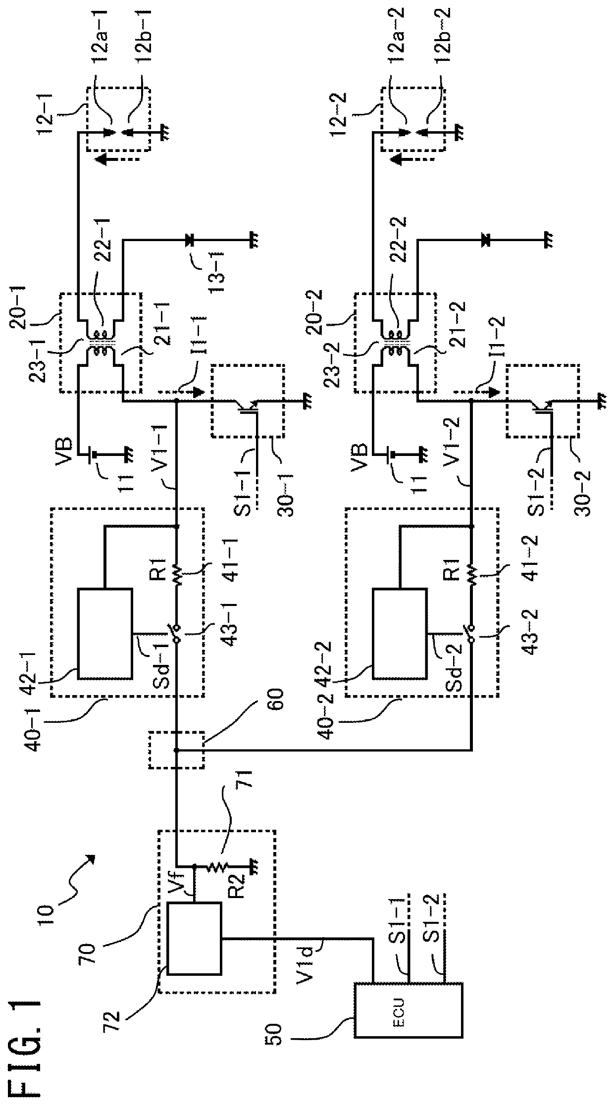
[0087]FIG. 4 is a configuration diagram showing the ignition apparatus for an internal combustion engine, according to Embodiment 2. For the configuration elements that are the same as the configuration elements shown in FIG. 1, the same numerals are given, so that detailed description thereof will be omitted.

[0088]As shown in FIG. 4, the configuration is the same as that of Embodiment 1 except that the sensing terminals of the primary-voltage-signal controllers 42-1, 42-2 are connected so as to be able to detect the command signal S1-1 and the command signal S1-2.

[0089]In the following, the configuration elements related to the first cylinder will be described as representatives. The primary-voltage-signal controller 42-1 controls the signal switching device 43-1 to be set to ON state during a preset fixed period from the time at which t...

embodiment 3

3. Embodiment 3

[0111]

[0112]Next, description will be made about an ignition apparatus for an internal combustion engine, according to Embodiment 3.

[0113]FIG. 6 is a configuration diagram showing the ignition apparatus for an internal combustion engine, according to Embodiment 3. For the configuration elements that are the same as the configuration elements shown in FIG. 1, the same numerals are given, so that detailed description thereof will be omitted.

[0114]As shown in FIG. 6, the configuration is the same as that of Embodiment 1 except for the primary-voltage-signal separators 40-1, 40-2.

[0115]In Embodiment 3, the primary-voltage-signal separators 40-1, 40-2 are configured with the high-voltage side resistances 41-1, 41-2 and bidirectional Zener diodes 44-1, 44-2, respectively.

[0116]In the following, the configuration elements related to the first cylinder will be described as representatives. Because the bidirectional Zener diode 44-1 is placed, in the periods where the generati...

embodiment 4

4. Embodiment 4

[0134]

[0135]FIG. 8 is a configuration diagram showing an ignition apparatus for an internal combustion engine, according to Embodiment 4. For the configuration elements that are the same as the configuration elements shown in FIG. 1, the same numerals are given, so that detailed description thereof will be omitted.

[0136]As shown in FIG. 8, the configuration is the same as that of Embodiment 1 except for the primary-voltage-signal separators 40-1, 40-2 and the primary-voltage-information detector 70.

[0137]In Embodiment 4, the primary-voltage-signal separators 40-1, 40-2 have a configuration in which the primary-voltage-signal controllers 42-1, 42-2 and the signal switching devices 43-1, 43-2 are eliminated, namely, they are configured only with the high-voltage side resistances 41-1, 41-2, and are thus simplified. It is appropriate that their resistance values are each set to a large value that is less influenced by another cylinder. For example, its level is from seve...


PUM


Abstract

An object is to reduce the required numbers of connector pins and A/D converters, without degrading the detection accuracy. There is provided an ignition apparatus which includes: ignition plugs provided for multiple cylinders; an ignition coil provided for each cylinder, and having a primary coil and a secondary coil magnetically coupled to the primary coil and connected to the ignition plug; switching devices each for switching between application and shut-off of current to the primary coil; a primary-voltage-signal separator provided for each cylinder, for inputting thereto a voltage of the primary coil and outputting the voltage as a primary signal; a primary-signal combiner for electrically combining together each primary signal corresponding to each cylinder, to thereby output a composite primary signal; and a primary-voltage-information detector for inputting thereto the composite primary signal, to thereby output primary voltage information of each cylinder.

Description

BACKGROUND OF THE INVENTION1. Field of the Invention[0001]The present application relates to an ignition apparatus.2. Description of the Background Art[0002]In spark-ignition type internal combustion engines, in many cases, an air-fuel mixture in the combustion chamber is combusted in such a manner that a current is applied to a primary coil and is then shut off, thereby to induce a secondary voltage in a secondary coil magnetically coupled thereto and then to generate a high-voltage arc in the ignition plug provided in the combustion chamber and connected to the secondary coil.[0003]There is proposed a method in which a breakdown voltage of the ignition plug on that occasion is measured and used for controlling the internal combustion engine. The breakdown voltage is a secondary voltage induced on the secondary-coil side of the ignition coil, at the moment when breakdown occurs between the electrodes of the ignition plug. The behavior of the secondary voltage is correlated with the...

Claims


Application Information

Patent Timeline
Patent Type & Authority Applications(United States)
IPC IPC(8): F02P3/055F02P7/077
CPCF02P3/0554F02P17/12F02P7/077
Inventor NAKAMURA, TOSHIFUMIINADA, TAKAHIKO
Owner MITSUBISHI ELECTRIC CORP
Why Eureka
Try Eureka