
Semiconductor device with semiconductor chip formed by using wide gap semiconductor as base material

a technology of semiconductor chip and base material, which is applied in the direction of semiconductor device, semiconductor/solid-state device details, electrical apparatus, etc., can solve the problems that the cost reduction of the semiconductor device cannot be achieved, and achieve the reduction of the size, weight and cost of the module element, and simplify the cooling mechanism of the element. , the effect of wide gap

Inactive Publication Date: 2006-06-06
MITSUBISHI ELECTRIC CORP
View PDF7 Cites 1 Cited by
  • Summary
  • Abstract
  • Description
  • Claims
  • Application Information

AI Technical Summary

Benefits of technology

This configuration simplifies the cooling mechanism, reduces the size and weight of the semiconductor device, and allows the wide gap semiconductor chip to operate effectively at higher temperatures, achieving significant reductions in device size, weight, and cost while maintaining performance.

Problems solved by technology

Accordingly, even if the chips in the module element with the configuration of FIG. 9 are replaced by wide gap semiconductor chips, reductions in the cost of the semiconductor device cannot be achieved.

Method used


Image

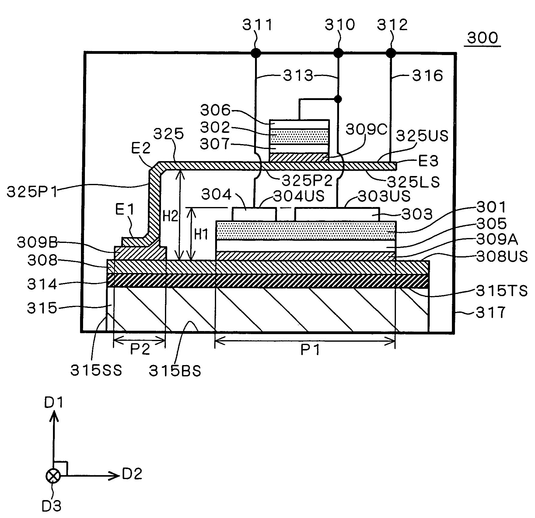
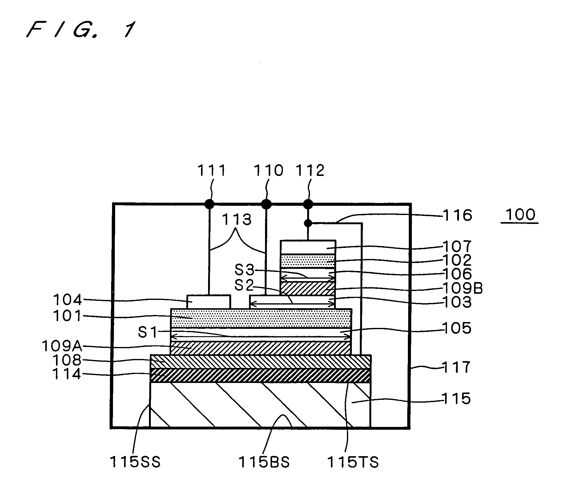
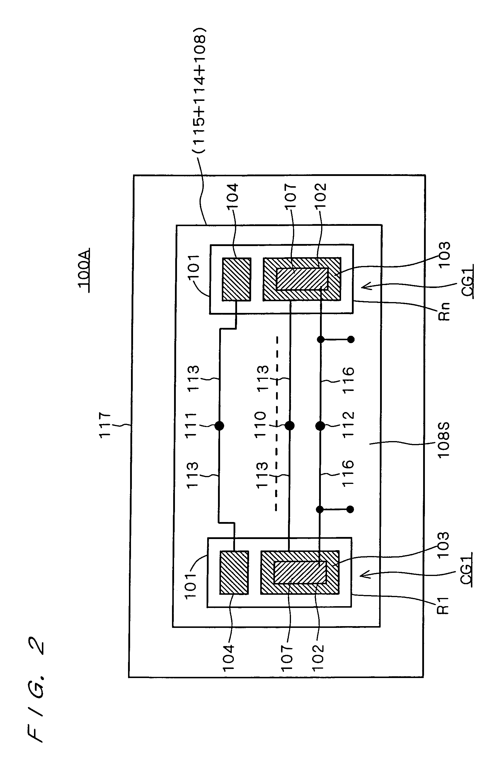
  • Semiconductor device with semiconductor chip formed by using wide gap semiconductor as base material
  • Semiconductor device with semiconductor chip formed by using wide gap semiconductor as base material
  • Semiconductor device with semiconductor chip formed by using wide gap semiconductor as base material

Examples


Embodiment Construction

[0026]A wide gap semiconductor of, for example, silicon carbide or gallium nitride is receiving attention as a base material for semiconductor chips, as an alternative to silicon. Its advantages are the following.

[0027]First of all, a wide gap semiconductor such as silicon carbide or gallium nitride has a great interband energy gap and thus has high thermal stability, as compared with silicon. That is, a device manufactured by using silicon carbide or gallium nitride as the base material is capable of operation even at a high temperature of 1000 Kelvin. By utilizing this feature of being operable at high temperatures, more specifically, by locating a semiconductor chip of wide gap semiconductor such as silicon carbide or gallium nitride (wide gap semiconductor chip) in a portion of a closed container where the cooling effect is relatively small, a higher density of device configuration and accordingly a simpler element cooling mechanism, e.g., a heat sink, can be expected.

[0028]Seco...


PUM


Abstract

A switching chip using silicon as the base material is located on the upper surface of a cooling mechanism formed of a heat sink, an insulating substrate and a conductive plate, with a first conductive layer sandwiched in between. Further, a diode chip having a smaller area than a cathode electrode and using a wide gap semiconductor as the base material is located on the cathode electrode which has a smaller area than an anode electrode, with a second conductive layer sandwiched in between. A closed container encloses every structural component except an exposed portion of a bottom surface in the interior space.

Description

CROSS-REFERENCE TO RELATED APPLICATIONS[0001]This application is a divisional of U.S. patent application Ser. No. 10 / 786,095, filed Feb. 26, 2004, now U.S. Pat. No. 6,861,730 which is a divisional of U.S. patent application Ser. No. 10 / 208,980 filed Aug. 1, 2002, which issued as U.S. Pat. No. 6,831,351, on Dec. 14, 2004, which in turn claims priority to Japan Patent 2002-044666, filed Feb. 21, 2002, the entire contents of each of which are hereby incorporated herein by reference.BACKGROUND OF THE INVENTION[0002]1. Field of the Invention[0003]The present invention relates to a semiconductor device comprising first and second semiconductor chips which are contained in a single package and at least one of which is formed by using a wide gap semiconductor (such as silicon carbide or gallium nitride) as the base material. The following description of the present invention centers mainly on semiconductor devices for use in high voltage applications; however, the present invention is not l...

Claims


Application Information

Patent Timeline
Patent Type & Authority Patents(United States)
IPC IPC(8): H01L23/02H01L23/34H01L21/52H01L23/051H01L23/36H01L25/07H01L25/18
CPCH01L23/051H01L23/36H01L25/072H01L25/18H01L2924/13055H01L2924/0002H01L2924/13091H01L2924/00
Inventor HIRAO, MASAYOSHISATOU, KATSUMITOOI, SHIGEOMATSUO, KAZUSHIGE
Owner MITSUBISHI ELECTRIC CORP
Learn More