Chain motor power distribution and control

a technology of chain motors and power distribution, applied in the direction of portable lifting, hoisting equipment, and conversion without intermediate conversion to dc, can solve the problems of lagging chains, difficult to ship them still attached, and distros lack features to improve the safety and efficiency of chain motor use. , to achieve the effect of improving the safety and efficiency of chain motor operation

Pending Publication Date: 2022-10-13
CALLAHAN MICHAEL
View PDF0 Cites 0 Cited by
  • Summary
  • Abstract
  • Description
  • Claims
  • Application Information

AI Technical Summary

Benefits of technology

[0010]In another aspect, improvements are disclosed for improving the safety and efficiency of chain motor operation.

Problems solved by technology

The distro for a group of motors supporting the same large production element is often preferably mounted to that element, but distro size and weight have made difficult shipping them still attached.
And, such distros have lacked features improving the safety and efficiency of chain motor use.

Method used


Image

  • Chain motor power distribution and control
  • Chain motor power distribution and control
  • Chain motor power distribution and control

Examples


Embodiment Construction

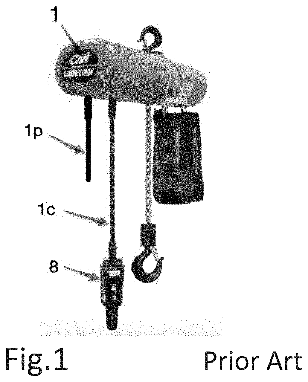
[0087]Refer now to FIG. 1, which illustrates a chain motor as manufactured by Columbus-McKinnon of Getzville, N.Y., the most popular U.S. brand; its “Model L”, with a 1-ton lifting capacity, being its most popular model.

[0088]Chain motors require AC power for operation, typically a three-phase 120 / 208-volt circuit. In some cases, motors are actuated solely by applying power to them, with the direction of chain travel determined by the applied phase rotation. This, however, requires that each motor be provided with a unique circuit connecting it with power relays at another location.

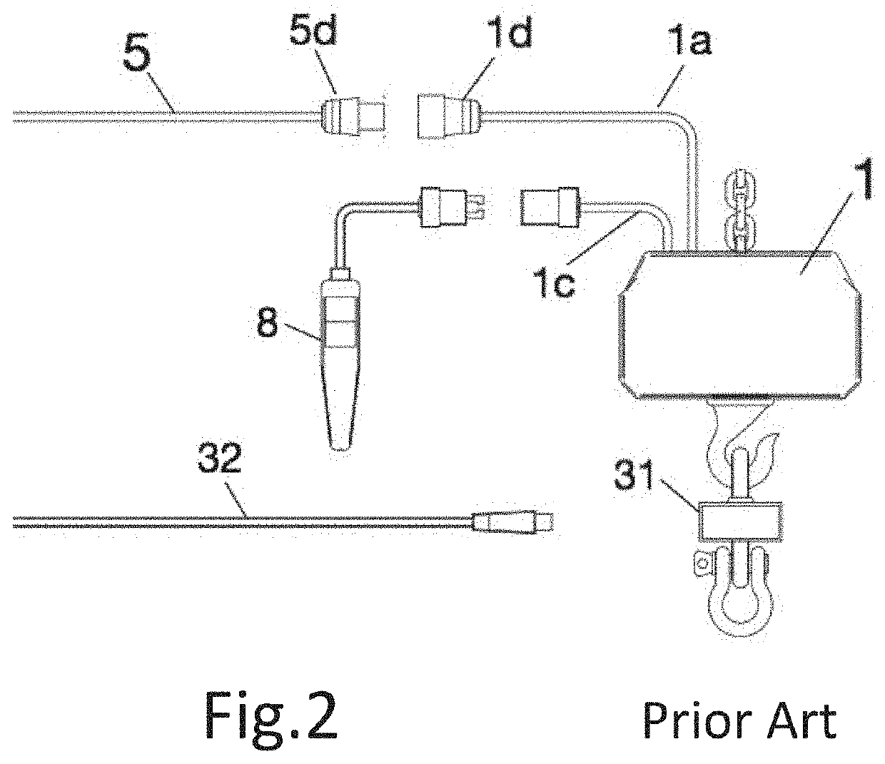
[0089]More commonly, power relays are mounted inside the motor, such that multiple motors can share the same AC supply and each motor can be controlled by switch closures both locally (e.g., by “pickle”8) and remotely via low current wiring. Motors equipped with internal relays are typically sold with a power pigtail 1p for their alternating current supply and a second pigtail 1c terminating in a “pickle”...


PUM


Abstract

Units for distributing three-phase power to a plurality of chain motors are provided, as are used to raise and suspend production elements such as lighting, sound, video, and scenery. Remote switching and phase reversal of such power are also provided. In the prior art, such switching has been performed by large, heavy contactors inserted between the single power input and its distribution to plural outputs for motors, making the unit difficult to handle and ship. Provided herein are power switching and phase reversal performed by a plurality of parallel such means, reducing the current requirements for each, and thereby the size, weight, and cost of the whole. In some embodiments, the single power input is replaced by a by a cable delivering a plurality of two-phase circuits to the unit which derives the three-phase circuits necessary for chain motors therefrom.

Description

[0001]This application is a continuation-in-part of U.S. Ser. No. 17 / 181,179, filed Feb. 22, 2021, which claims priority to U.S. Provisional Application Ser. No. 62 / 979,762, filed Feb. 21, 2020, the entire disclosure of which is hereby incorporated by reference.[0002]This application is related to U.S. Provisional Application No. 61 / 973,592, filed Apr. 1, 2014; U.S. Utility application Ser. No. 14 / 676,616, filed Apr. 1, 2015; Utility application Ser. No. 15 / 614,902, filed Jun. 6, 2017; U.S. Utility application Ser. No. 15 / 945,987, filed Apr. 5, 2018; U.S. Provisional Application No. 62 / 743,095, filed Oct. 9, 2018; U.S. Utility application Ser. No. 16 / 253,620, filed Jan. 22, 2019; U.S. Utility application Ser. No. 16 / 596,002, filed Oct. 9, 2019; U.S. Utility application Ser. No. 17 / 069,054, filed Oct. 13, 2020; U.S. Utility application Ser. No. 17 / 508,194, filed Oct. 22, 2021; and U.S. Utility application Ser. No. 17 / 508,209, filed Oct. 22, 2021, the entire disclosures of the followi...

Claims


Application Information

Patent Timeline
Patent Type & Authority Applications(United States)
IPC IPC(8): B66D1/12H02M5/14B66D1/46
CPCB66D1/12H02M5/14B66D1/46B66D2700/0141B66D3/18B66D3/26
Inventor CALLAHAN, MICHAEL
Owner CALLAHAN MICHAEL
Why Eureka
Try Eureka