Flexible display device and method for manufacturing the same

a display device and flexible technology, applied in the field of flexible display devices, can solve the problems of reducing the width in the non-display area, and achieve the effects of reducing the width of the bezel, reducing the width of the non-display area, and improving product valu

Active Publication Date: 2014-12-04
LG DISPLAY CO LTD
View PDF5 Cites 98 Cited by
  • Summary
  • Abstract
  • Description
  • Claims
  • Application Information

AI Technical Summary

Benefits of technology

[0016]The flexible display device according to the embodiments of the present invention can reduce a width of a bezel without reducing a width of the non-display area, since the plurality of pads are disposed on the lower surface of the substrate by bending the bending area. Accordingly, the display devices have improved product values associated with aesthetics and usability.
[0017]The flexible display device includes the first bending hole, thus enabling removal of parts of each the buffer film, the gate insulation film and the interlayer insulation film which correspond to the bending area. As a result, it is possible to prevent problems such as application of relatively greater bending stress to the buffer film, the gate insul

Problems solved by technology

However, disadvantageously, there is a limitation to reduction of width in the non-display area due to areas c

Method used


Image

  • Flexible display device and method for manufacturing the same
  • Flexible display device and method for manufacturing the same
  • Flexible display device and method for manufacturing the same

Examples


first embodiment

[0037]First, a flexible display device according to the present invention will be described with reference to FIGS. 1 to 6.

[0038]FIG. 1 is a plan view illustrating a flexible display device according to the first embodiment of the present invention. FIG. 2 is a sectional view illustrating a pixel area according to the first embodiment of the present invention. FIG. 3 is a sectional view illustrating a state in which a bending area of a substrate is bent in the flexible display device of FIG. 1. FIG. 4 is a plan view illustrating a part I of FIG. 1. FIG. 5 is a sectional view illustrating a part II-II′ of FIG. 4. FIG. 6 is a sectional view illustrating a part III-III′ of FIG. 4.

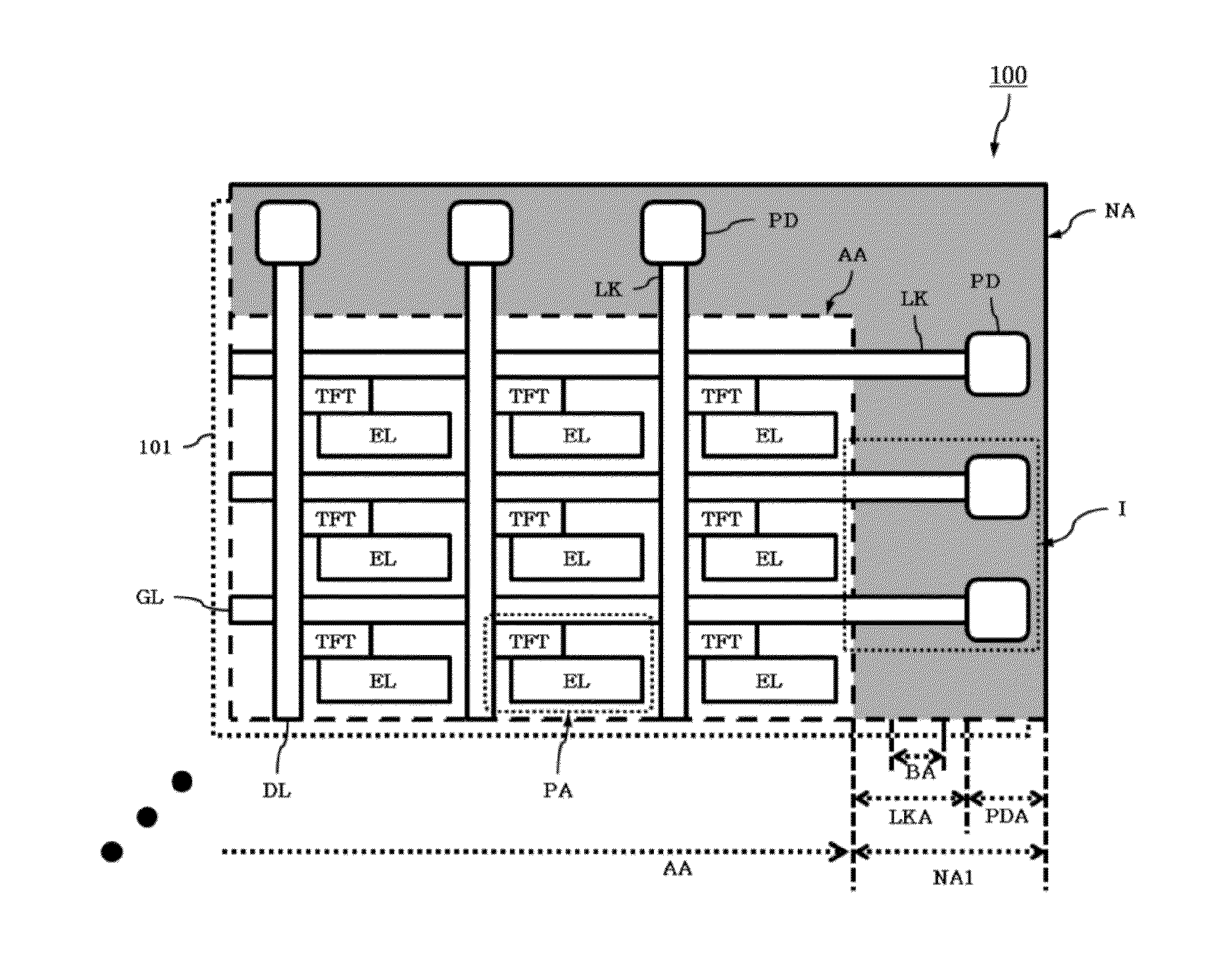
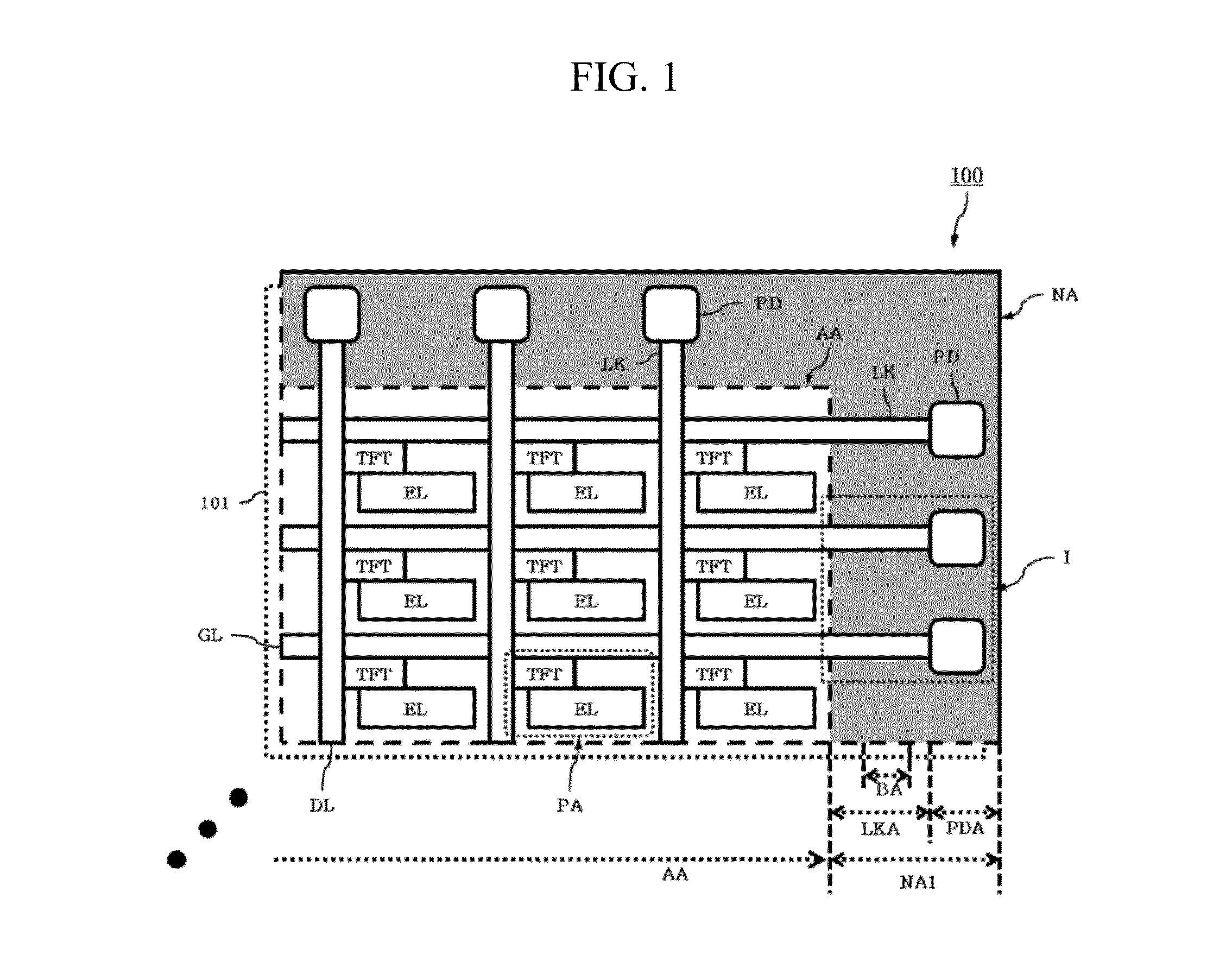
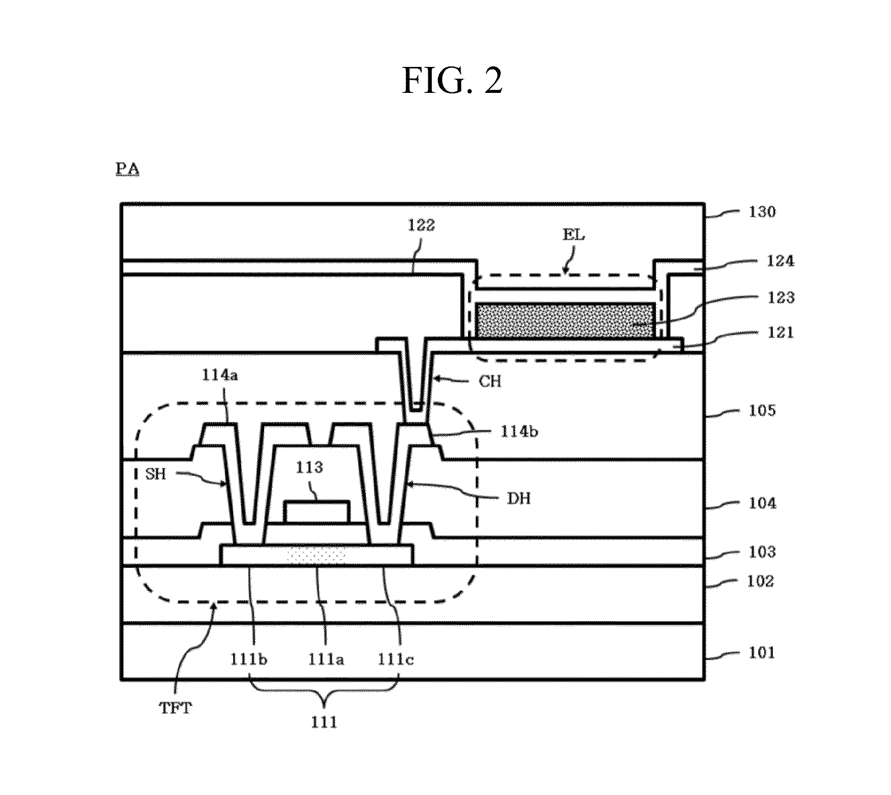
[0039]As shown in FIG. 1, the flexible display device 100 according to the first embodiment of the present invention includes: a substrate 101; a plurality of gate lines GLs and a plurality of data lines DLs; a plurality of pads PD; a plurality of links LK; and insulation films 102, 103, 104 and 105 (not shown...

second embodiment

[0086]Next, the flexible display device according to the present invention will be described with reference to FIGS. 7 and 8.

[0087]FIG. 7 is a plan view illustrating the part I of FIG. 1 according to the second embodiment of the present invention in more detail. FIG. 8 is a sectional view illustrating the part IV-IV′ of FIG. 7.

[0088]As shown in FIGS. 7 and 8, the flexible display device according to the second embodiment further includes at least one second bending hole BH2. The second bending hole BH2 is formed in the periphery of the link LK in each first bending hole BH1. The other portions are the same as the flexible display device of the first embodiment shown in FIGS. 1 to 6. An overlapping description thereof is thus omitted below.

[0089]Each second bending hole BH2 shown in FIGS. 7 and 8 is used for removal of bending stress factors, that is, the protective film 105 and the anti-etching layer 106 left in the periphery of the link LK in the first bending hole BH1. In other wo...

third embodiment

[0091]Next, the present invention will be described with reference to FIG. 9.

[0092]FIG. 9 is a sectional view illustrating the part II-IP of FIG. 4 according to the third embodiment of the present invention.

[0093]As shown in FIG. 9, the flexible display device according to the third embodiment further includes a pre-bending hole pre_BH1. The pre-bending hole pre_BH1 is formed after formation of the buffer film 102 and before formation of the active layer 111 to correspond to the bending area BA and to pass through the buffer film 102 in a width greater than the first bending hole BH1. The other portions are the same as that of the first or second embodiment. An overlapping description thereof is thus omitted below.

[0094]Forming the pre-bending hole pre_BH1 shown in FIG. 9 results in removing the buffer film 102 in the bending area prior to the formation of the first bending hole BH1. Accordingly, it is not necessary to remove the buffer film 102 anymore in forming the first bending ...


PUM


Abstract

Discussed is a flexible display device to reduce a width of a bezel. The flexible display device includes a substrate being formed of a flexible material, a plurality of gate lines and a plurality of data lines crossing each other, a plurality of pads formed in a pad area of a non-display area, a plurality of links formed in a link area of the non-display area, a plurality of insulation films formed over the entire surface of the substrate, and a first bending hole formed in a bending area of the non-display area, the first bending hole passing through at least one of the insulation films disposed under the link, wherein the bending area is bent such that the pads are disposed on the lower surface of the substrate.

Description

[0001]This application claims the benefit of Korean Patent Application No. 10-2013-0060169, filed on May 28, 2013, which is hereby incorporated by reference as if fully set forth herein.BACKGROUND OF THE INVENTION[0002]1. Field of the Invention[0003]The present invention relates to a flexible display device and a method for manufacturing the same to reduce a width of a peripheral edge area (i.e., bezel) of a display area.[0004]2. Discussion of the Related Art[0005]As part of the evolution of the information age, the field of displays to visually display electric information signals is rapidly growing. In response to this trend, a great deal of research to increase performance such as slimness, weight reduction and low power consumption of various flat display devices continues.[0006]Representative examples of flat display devices include liquid crystal displays (LCDs), plasma display panels (PDPs), field emission displays (FEDs), electro-luminescent displays (ELDs), electrowetting d...

Claims


Application Information

Patent Timeline
IPC IPC(8): H01L27/12
CPCH01L27/1259H01L27/124Y02E10/549H01L24/06H01L2924/12044H01L2924/12041Y02P70/50H10K59/179H10K59/131H10K77/111H01L2924/00G09F9/30
Inventor YOUN, SANG-CHEONJIN, HYOUNG-SUKKANG, CHANG-HEONKWON, SE-YEOUL
Owner LG DISPLAY CO LTD
Why Eureka
Try Eureka