Method For Measuring Scattered Light And Apparatus For Measuring Scattered Light

a technology of scattered light and measurement apparatus, applied in the field of light, can solve the problems of detection errors, measurement inaccuracies or errors, and ever more stringent demands for measuring accuracy, and achieve the effect of simplifying measurement and improving accuracy and reproducibility of signal values

Active Publication Date: 2014-12-04
POSTNOVA ANALYTICS
View PDF9 Cites 5 Cited by
  • Summary
  • Abstract
  • Description
  • Claims
  • Application Information

AI Technical Summary

Benefits of technology

[0013]In particular, signal peaks caused by impurities—so-called peaks or spikes—can be disregarded on the basis of the plurality of scattered light signals detected at different angles of rotation so that a corrected signal value can be determined. This enables less elaborate storage or cleaning of the measuring cell. Excessive scattered light signals, which result from (the smallest of) air pockets in the measuring cell material or in the sample, can also be corrected in this way. By means of the present invention the measurement is therefore simplified because, for example, the samples require less elaborate preparation.
[0014]Thus, by rotating the measuring cell during the measurement and by detecting scattered light signals at different angles of rotation of the measuring cell, the accuracy and reproducibility of the signal value can be considerably improved.

Problems solved by technology

However, ever more stringent demands are being made as regards measuring accuracy.
In particular, the measuring cell can be the cause of measuring inaccuracies or errors.
On the other hand, the smallest of impurities in the material of the measuring cell or on the surface of the measuring cell and in the sample itself also lead to detection errors, the impurities being particles with a size in the nm / gm range.
In this way, the laser beam is scattered more greatly at the impurities than by the sample, and a signal value that is very prone to error is achieved.
Also the smallest of air pockets in the sample material which are located in the laser's beam path lead to excessive scattering, and this additionally hinders measurement.

Method used


Image

  • Method For Measuring Scattered Light And Apparatus For Measuring Scattered Light
  • Method For Measuring Scattered Light And Apparatus For Measuring Scattered Light
  • Method For Measuring Scattered Light And Apparatus For Measuring Scattered Light

Examples


Embodiment Construction

[0009]It is therefore the object of the present invention to increase measuring accuracy when measuring static light scattering with a simple structure, and in particular to reduce or prevent measuring errors associated with the measuring cell and / or the sample.

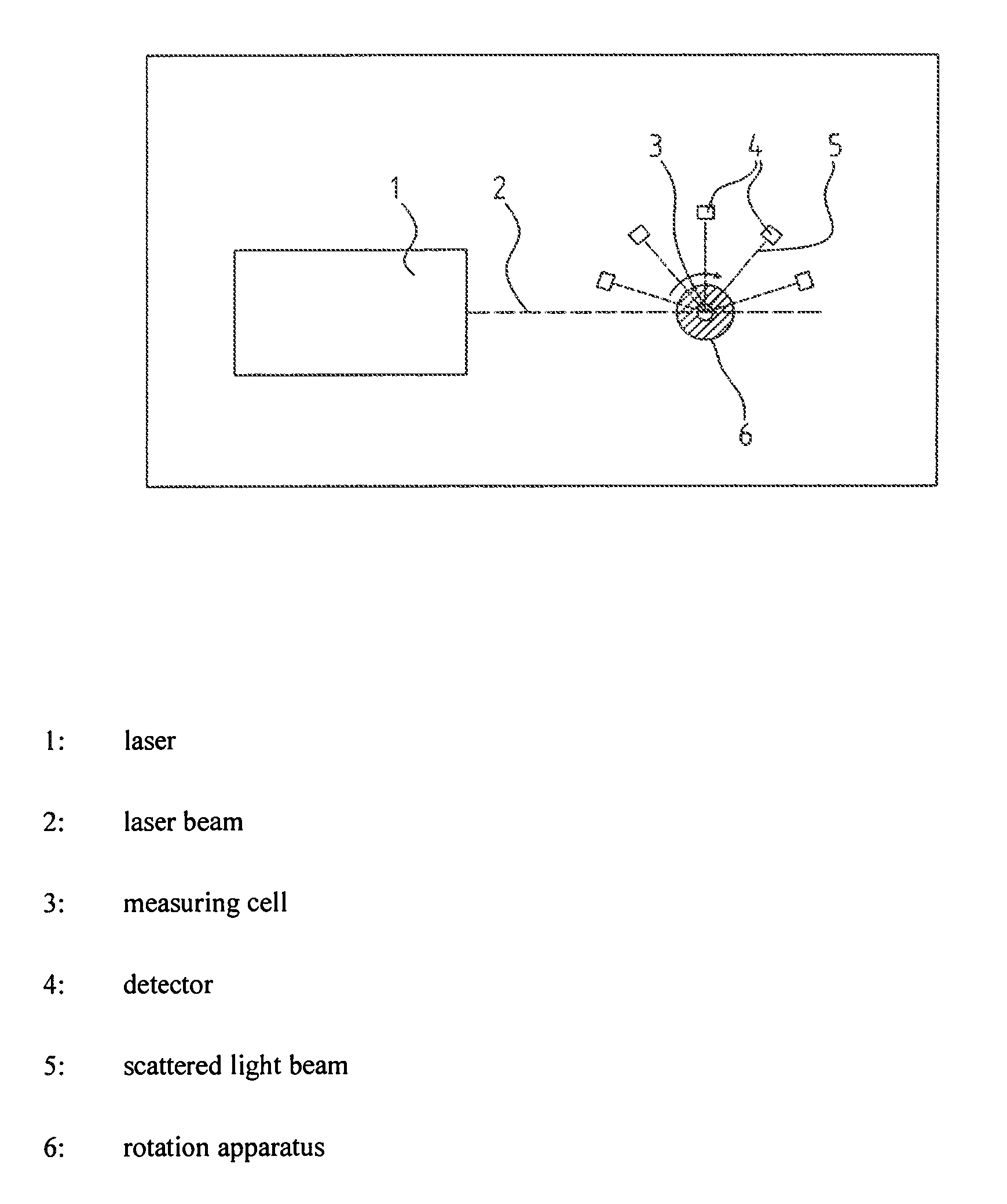
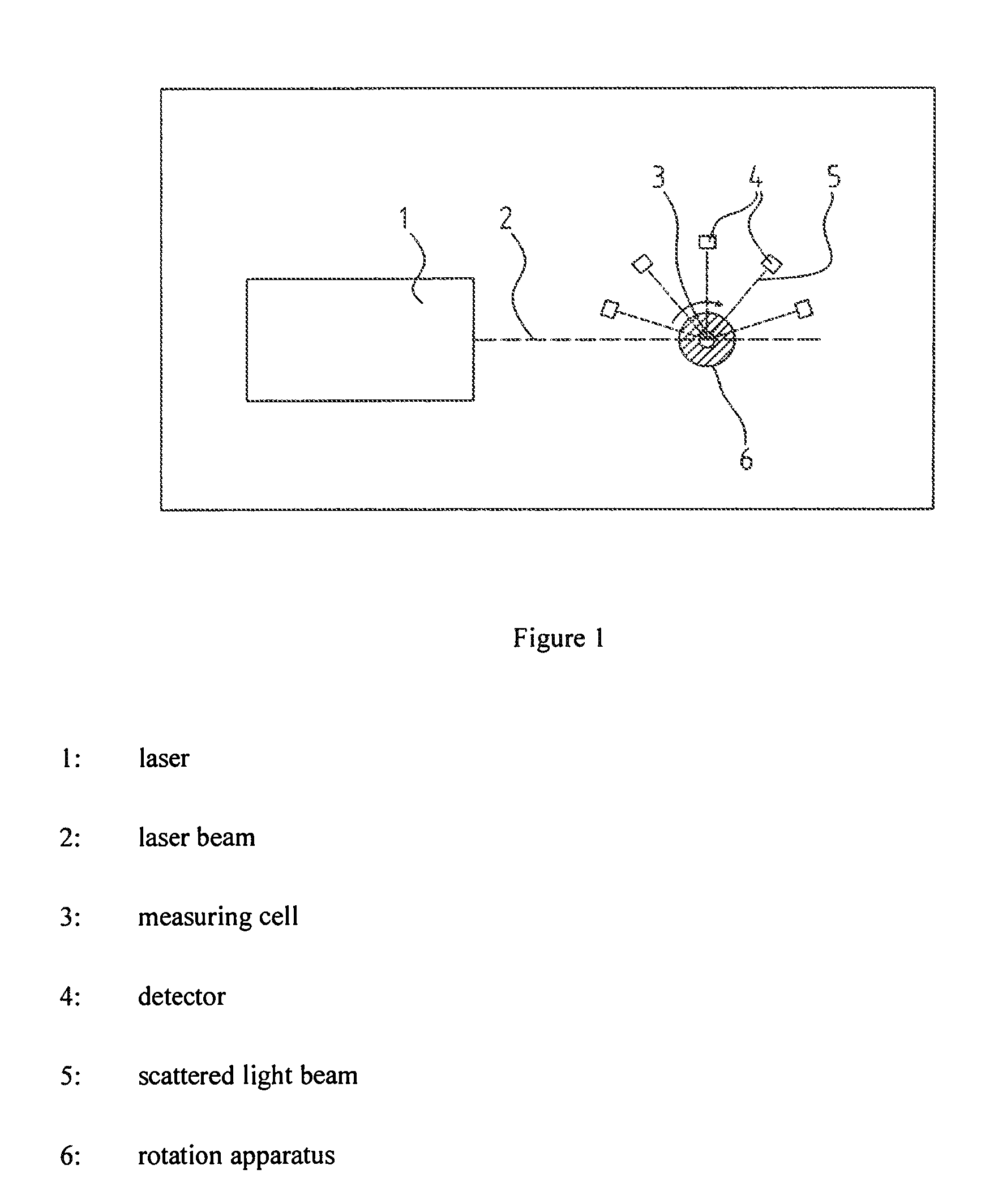
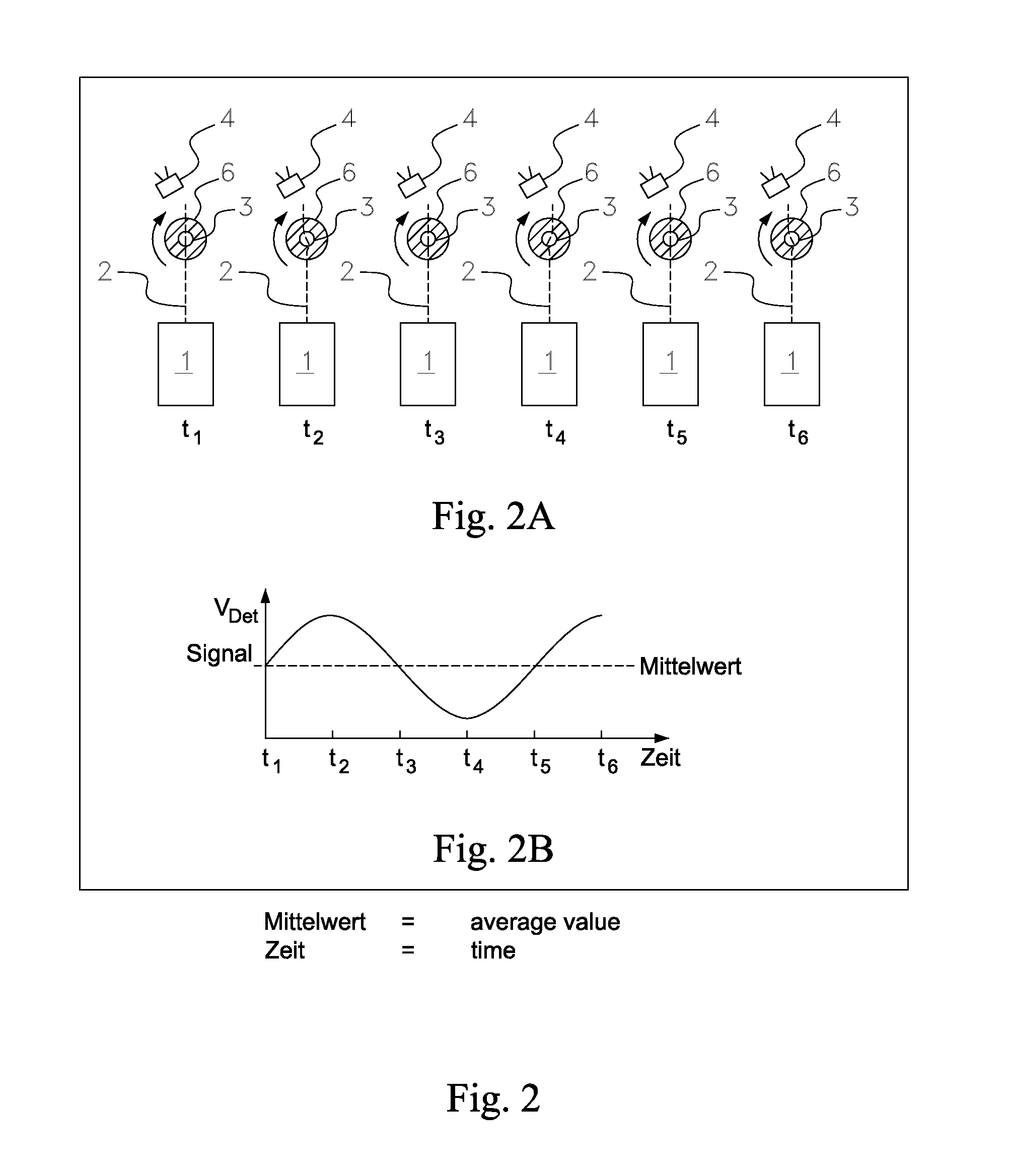
[0010]According to the invention, this object is achieved by the method having the features of claim 1. Accordingly, the following steps are provided for measuring light scattered on a sample in a medium, in particular a fluid medium: providing a rotatably arranged measuring cell with a substantially circular cross-section in a plane perpendicular to the axis of rotation for receiving the medium and the sample, rotating the measuring cell, preferably at least once by substantially 360°, about the axis of rotation, preferably by means of a drive, emitting a laser beam by means of a laser onto the sample located within the measuring cell in the plane perpendicular to the axis of rotation at different angles of rotation of the m...


PUM

PropertyMeasurementUnit
anglesaaaaaaaaaa
detection angleaaaaaaaaaa
wavelengthaaaaaaaaaa

Abstract

The invention provides a method for measuring light scattered on a sample in a medium, in particular a fluid medium, that comprises the following steps: providing a rotatably arranged measuring cell with a substantially circular cross-section in a plane perpendicular to the axis of rotation for receiving the medium and the sample, rotating the measuring cell, preferably at least once by substantially 360°, about the axis of rotation, in particular by means of a drive, emitting a laser beam by means of a laser onto the sample located within the measuring cell in the plane perpendicular to the axis of rotation at different angles of rotation of the measuring cell, the measuring cell maintaining its position in the direction of the axis of rotation, detecting scattered light signals by means of at least two detectors arranged in a circle and concentrically to the centre of rotation of the measuring cell and fixed within set, different angular ranges at different angles of rotation of the measuring cell, and determining a corrected signal value for each detector on the basis of the scattered light signals detected at different angles of rotation of the measuring cell for each detector. Furthermore, the invention provides an apparatus for measuring light scattered on a sample according to the method comprising a laser, a measuring cell and a detector.

Description

TECHNICAL FIELD[0001]The invention relates to a method for measuring light scattered on a sample in a medium, in particular a fluid medium, a laser beam being emitted onto a sample located within a measuring cell and the scattered light being detected by a detector. Furthermore, the invention relates to an apparatus for measuring light scattered on a sample in a medium, in particular a fluid medium, according to the method, comprising a laser, a measuring cell and a detector.PRIOR ART[0002]This type of method is widely used in static light scattering measurement. Static light scattering measurement is used for characterisation with regard to the size, mass, form and structure of molecules or colloidal substances. This is an absolute method which gets by without any previous calibration or use of standard samples.[0003]In order to illustrate the scattering of light, a suspension is observed in which there are a number of macromolecules and which is illuminated with a laser beam. The ...

Claims


Application Information

Patent Timeline
Patent Type & Authority Applications(United States)
IPC IPC(8): G01J1/42G01J1/08G01N15/02
CPCG01J1/42G01J2001/4295G01J1/08G01N15/0205G01N21/51G01N2021/4707G01N2021/4711
Inventor WELZ, ROLAND
Owner POSTNOVA ANALYTICS
Why Eureka
Try Eureka