Single-phase power converter, three-phase two-phase power converter, and three-phase power converter

a power converter and three-phase technology, applied in the direction of power conversion systems, ac-dc conversion, electrical equipment, etc., can solve the problems of devices being larger and heavier, and achieve the effects of simple structure, low price, and high efficiency

Active Publication Date: 2014-12-04
TOKYO INST OF TECH
View PDF7 Cites 18 Cited by
  • Summary
  • Abstract
  • Description
  • Claims
  • Application Information

AI Technical Summary

Benefits of technology

[0044]According to the present invention, a single-phase power converter, three-phase to two-phase power converter, and three-phase power converter that bidirectionally convert DC and AC and that are small, simply-structured, low-priced, and highly efficient can be realized.
[0045]Using the single-phase power converter, three-phase to two-phase power converter, and three-phase power converter, a battery energy storage device can be interconnected to an electric power system without using a converter transformer, and thus the device can be smaller and lighter.
[0046]Moreover, the conventional modular multilevel converter has a problem in that the interconnection transformer cannot be eliminated in view of voltage matching and electric insulation, while, according to the present invention, since a DC power supply with low voltage and large current can be interconnected to an electric power system, the electric insulating structure on the DC side can be constructed more easily than when the conventional modular multilevel converter is used.
[0047]The three-phase power converter according to the present invention is optimum in terms of use for a battery energy storage device that has low voltage and large current on the DC side, since the three-phase power converter can be interconnected to a system with half the DC voltage compared with the conventional three-phase modular multilevel cascade converters described in Patent Literature 1 and Non-Patent Literature 1 to 4, and the electric insulating structure on the DC side can be easily constructed.
[0048]As such, by realizing the interconnection with half the DC voltage of the conventional techniques, the following advantages can be obtained: First, in principle, as a characteristic of an assembled battery, reliability is higher as the voltage is lower. The present invention offers an advantage of high reliability as the interconnection is realized with half the DC voltage. Secondly, there is an advantage in that, since the DC voltage is lower, the applicability of existing techniques increases. Specifically, if the DC voltage level is lowered, for example, from 1500V to 700V by application of the present invention, the DC voltage level becomes closer to the low voltage electric equipment field wherein various existing techniques can be used. Thus, the applicability of the existing proven techniques increases, offering advantages in terms of enhancing the reliability and facilitating easier protection and insulation. For example, in a high voltage region of 2000V or more, the fields of application are limited, thus, there are problems in that: reliability is lowered; protection and insulation are difficult; and components such as voltage sensors and capacitors are expensive. These and other problems can be avoided by realizing interconnection with half the DC voltage by application of the present invention.
[0049]Further, since the three-phase power converter of the present invention also functions as an interconnection transformer, the three-phase power converter can be utilized as a small and low-cost power converter compared with conventional techniques for interconnecting to the electric power system.

Problems solved by technology

However, using such a converter transformer causes the device to be larger and heavier.

Method used


Image

  • Single-phase power converter, three-phase two-phase power converter, and three-phase power converter
  • Single-phase power converter, three-phase two-phase power converter, and three-phase power converter
  • Single-phase power converter, three-phase two-phase power converter, and three-phase power converter

Examples


Embodiment Construction

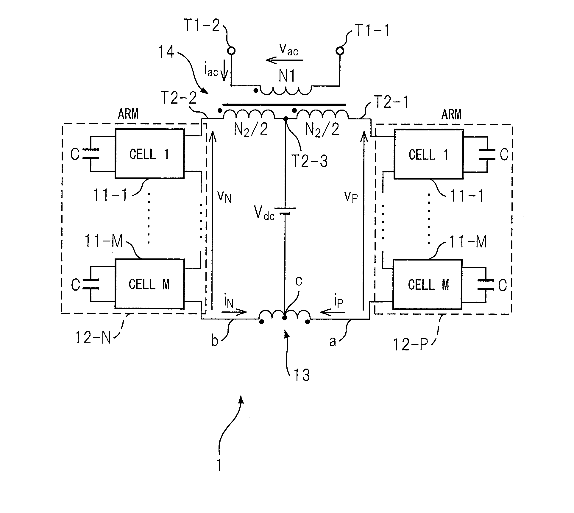
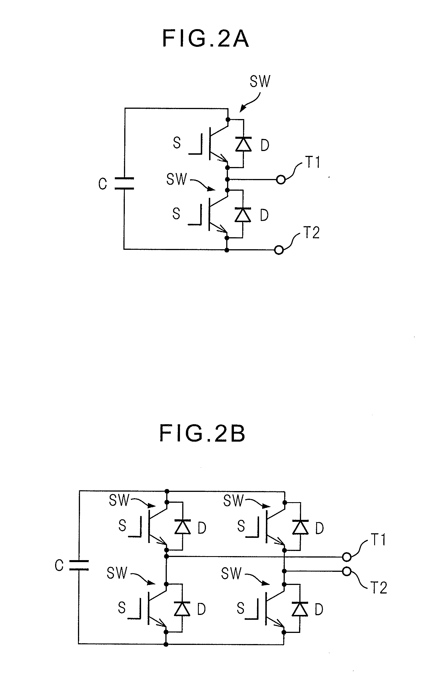
[0083]FIG. 1 is a circuit diagram depicting a single-phase power converter according to the first example. Hereinafter, the elements denoted by the same reference signs in different diagrams mean elements having the same functions. It should also be noted that, hereinafter, DC capacitors in the unit cells are described outside the unit cells for easy understanding. FIG. 2A is a circuit diagram depicting a chopper cell as a unit cell in the single-phase power converter according to the first to fifth examples. FIG. 2B is a circuit diagram depicting a bridge cell as a unit cell in the single-phase power converter according to the first to fifth examples.

[0084]The single-phase power converter according to the first example includes unit cells 11-1 to 11-M (where M is a natural number), a first arm 12-P, a second arm 12-N, an arm coupling unit 13, and a transformer 14.

[0085]The unit cells 11-1 to 11-M each have two semiconductor switches that are connected in series, a DC capacitor that...


PUM


Abstract

This power converter (1) is provided with: unit cells (11-M) having a semiconductor switch, a DC capacitor (C) and a charge / discharge current I / O terminal; a first arm (12-P) and a second arm (12-N) comprising multiple unit cells (11-M) connected to each other in cascade; an arm connecting unit (13) which has a first terminal to which the first arm (12-P) is connected, a second terminal to which the second arm (12-N) is connected, and a third terminal to which a DC power source is connected; and a transformer (14) which has an AC I / O terminal on the primary side and an intermediate terminal on the secondary side winding, and in which the terminal of the first arm (12-P) and the terminal of the second arm (12-N) are connected to the two end terminals on the secondary winding, and the DC power source (Vdc) is connected to the intermediate terminal.

Description

TECHNICAL FIELD[0001]The present invention relates to a single-phase power converter and a three-phase power converter that bidirectionally convert direct current (DC) and alternating current (AC), and a three-phase to two-phase power converter that bidirectionally converts three-phase AC and two-phase AC, and more particularly, relates to a single-phase power converter, three-phase to two-phase power converter, and three-phase power converter of modular multilevel type.BACKGROUND ART[0002]With increases in opportunities for introducing wind power and solar power generation, the importance of battery energy storage devices is ever increasing. FIG. 24 is a diagram depicting a general configuration of a battery energy storage device. The battery energy storage device 1000 includes: a battery 100, such as a Sodium Sulfur (NAS) battery and lithium ion battery, an interconnection converter 200 that converts DC voltage of the battery 100 to AC voltage; and an interconnection transformer 3...

Claims


Application Information

Patent Timeline
Patent Type & Authority Applications(United States)
IPC IPC(8): H02M7/797H02M7/497H02M7/537
CPCH02M7/797H02M7/497H02M7/537H02M7/483H02M7/53803H02M7/4835
Inventor AKAGI, HOROFUMIHAGIWARA, MAKOTO
Owner TOKYO INST OF TECH
Why Eureka
Try Eureka