Cell separation container

a cell and container technology, applied in the field of cell separation containers, can solve the problems of low efficiency of the cell dispersion device, and achieve the effects of not easily twisted, not easily unscrewed, and improved air tightness of the outer container and the inner container

Active Publication Date: 2014-12-04
JAPAN TISSUE ENG
View PDF2 Cites 10 Cited by
  • Summary
  • Abstract
  • Description
  • Claims
  • Application Information

AI Technical Summary

Benefits of technology

[0022]In the cell separation container including the outer container, the inner container, and the lid body, the lid body may include a lid main body that can be attached to and detached from the outer container by screwing and a rubber layer disposed inside the lid main body, and a rubber hardness of a surface of the rubber layer that is in contact with the lid main body may be higher than that of a surface of the rubber layer that is in contact with the outer container and / or the inner container. In this case, a friction is not easily produced between the rubber layer and the lid main body and thus the rubber layer is easily brought into close contact with the outer container and the inner container. Therefore, when the lid body is attached to the outer container, the rubber layer is not easily twisted and thus the lid is not easily unscrewed. Consequently, the air tightness of the outer container and the inner container can be further improved.

Problems solved by technology

However, the above-described device requires a large amount of dispersant-containing liquid because a sufficient amount of dispersant-containing liquid needs to be stored for treatment not only in the tissue holding member in which a cell dispersion treatment is performed but also in the liquid storage member.
Therefore, the efficiency of the cell dispersion device is not high.

Method used


Image

  • Cell separation container
  • Cell separation container
  • Cell separation container

Examples


first embodiment

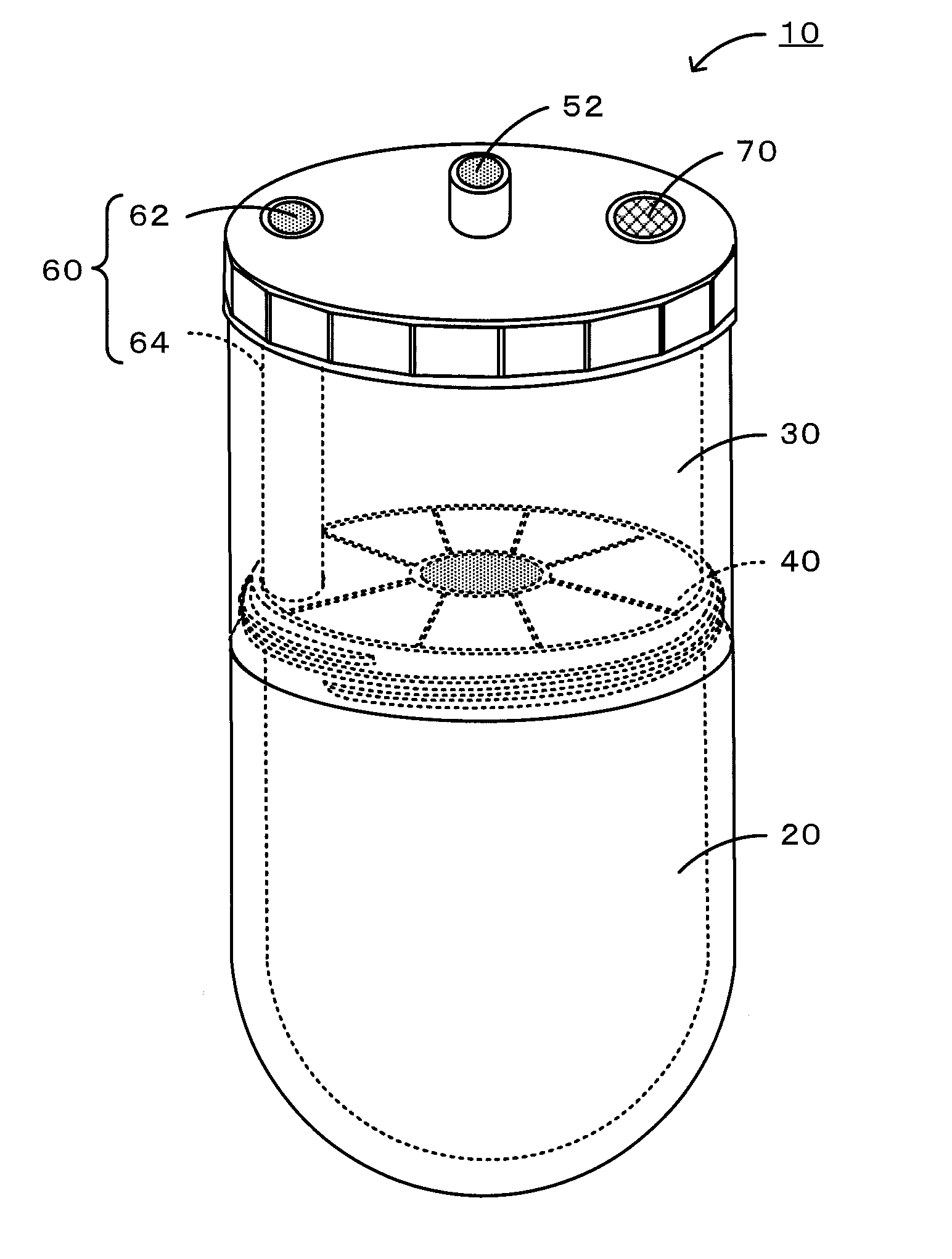
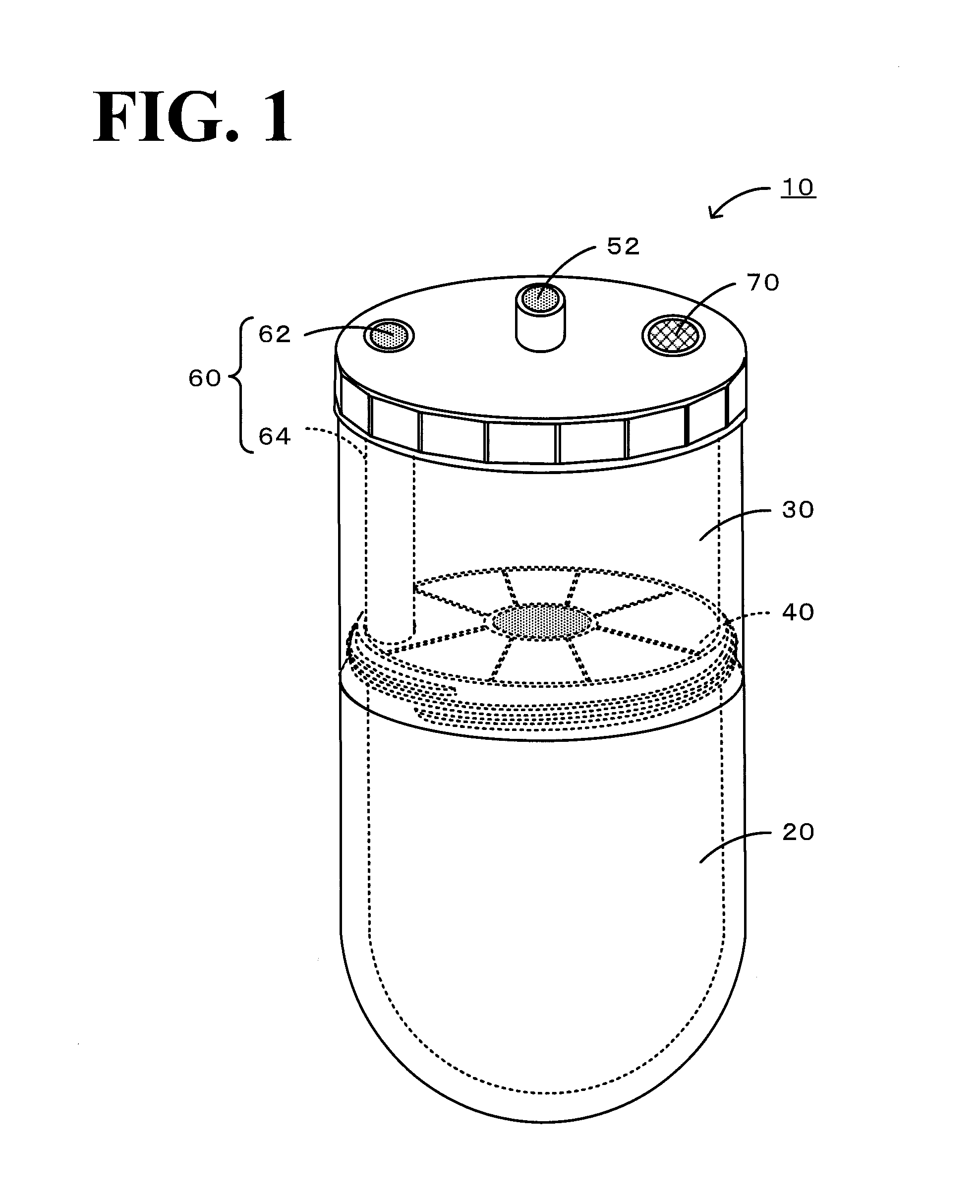
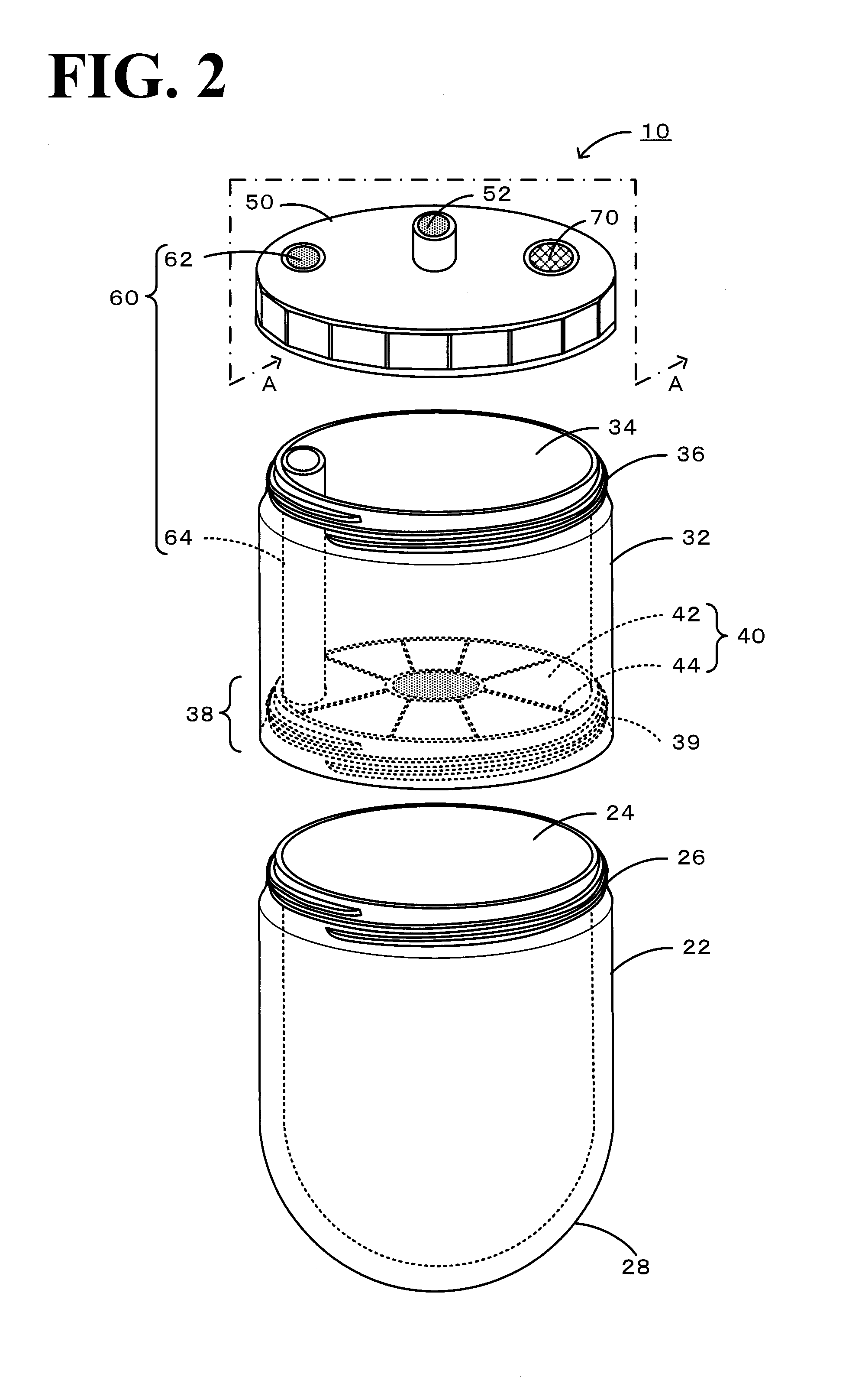
[0037]FIG. 1 is a perspective view of a cell separation container 10 according to a first embodiment. FIG. 2 is a perspective view of the cell separation container 10 before assembling. FIG. 3 is a schematic sectional view taken along line A-A in FIG. 2.

[0038]As shown in FIG. 1, the cell separation container 10 includes a collection chamber 20 and a tissue holding chamber 30 which are partitioned by a filter 40. The cell separation container 10 includes a first air pressure adjuster 60 configured to adjust the inflow and outflow of gas in the collection chamber 20 and a second air pressure adjuster 70 configured to adjust the inflow and outflow of gas in the tissue holding chamber 30. Thus, the inflow and outflow of the outside air and the gases in the collection chamber 20 and the tissue holding chamber 30 can be adjusted. As shown in FIG. 2, the cell separation container 10 includes a lower container 22, an upper container 32 including the filter 40, and a lid body 50 attachable t...

second embodiment

[0056]FIG. 9 is a perspective view of a cell separation container 310 according to a second embodiment. FIG. 10 is a perspective view of the cell separation container 310 before assembling.

[0057]As shown in FIG. 9, the cell separation container 310 includes a collection chamber 320 and a tissue holding chamber 330 which are partitioned by a filter 340. The cell separation container 310 includes a first air pressure adjuster 360 configured to adjust the inflow and outflow of gas in the collection chamber 320 and a second air pressure adjuster 370 configured to adjust the inflow and outflow of gas in the tissue holding chamber 330. Thus, the inflow and outflow of the outside air and the gases in the collection chamber 320 and the tissue holding chamber 330 can be adjusted. As shown in FIG. 10, the cell separation container 310 includes an outer container 322, an inner container 332 incorporated into an upper portion of the outer container 322, and a lid body 350 attachable to an outer...


PUM

PropertyMeasurementUnit
pore sizeaaaaaaaaaa
pore sizeaaaaaaaaaa
pore sizeaaaaaaaaaa

Abstract

A cell separation container includes a collection chamber and a tissue holding chamber which are partitioned by a filter. The cell separation container includes a first air pressure adjuster configured to adjust the inflow and outflow of gas in the collection chamber and a second air pressure adjuster configured to adjust the inflow and outflow of gas in the tissue holding chamber. Thus, the inflow and outflow of the outside air and the gases in the collection chamber and the tissue holding chamber can be adjusted. In the cell separation container, switching between holding a treatment liquid in the tissue holding chamber and ejecting a treatment liquid to the collection chamber can be performed by adjusting the inflow and outflow of the outside air and the gas in the connection chamber.

Description

TECHNICAL FIELD[0001]The present invention relates to a cell separation container.BACKGROUND ART[0002]In recent years, cell culture techniques have been used in various fields. For example, cells are cultured in vitro and the cultured cells are administered to patients in a treatment or are used in toxicity tests for drugs and the like. Such cell culture techniques have been used for a long time, but most of cell culture processes have involved manual operations, which impose a heavy burden on workers. Therefore, it is desirable to simplify or automate each operation. In particular, in an initial process of cell culture in which a cell is separated from a body tissue, many operations need to be performed, such as washing and disinfecting a body tissue biopsied from a patient or donor and separating a cell from the body tissue by performing a treatment with an enzyme-containing liquid. This imposes a heavy burden on workers.[0003]For example, PTL 1 discloses a cell dispersion device ...

Claims


Application Information

Patent Timeline
Patent Type & Authority Applications(United States)
IPC IPC(8): C12M1/00
CPCC12M47/04
Inventor SUGIURA, MAKOTO
Owner JAPAN TISSUE ENG
Why Eureka
Try Eureka