
Superconducting coil and superconducting device

a superconducting coil and superconducting coil technology, applied in the direction of superconducting magnets/coils, superconductor devices, magnetic bodies, etc., can solve the problems of difficult detection of quench, so as to minimize the number of steps of remanufacturing the pancake coil and repair the superconducting coil quickly, the effect of reducing the risk of serious damage in time and cos

Active Publication Date: 2014-12-04
THE FUJIKURA CABLE WORKS LTD
View PDF0 Cites 6 Cited by
  • Summary
  • Abstract
  • Description
  • Claims
  • Application Information

AI Technical Summary

Benefits of technology

The patent describes a superconducting coil that includes a cooling substrate with multiple cooling plates. This allows for easy separation of the coils, allowing for replacement of only the malfunctioning coil without wasting the entire coil. The cooling plates can be efficiently cooled using a freezing machine, ensuring good thermal conductivity. This design reduces damage to the superconducting wire and minimizes the time and cost of replacement or remanufacturing of the coil. Overall, this patent provides a solution for repairing superconducting coils quickly and at low cost.

Problems solved by technology

In this case, there is a risk of serious damage in terms of time and cost.
In particular, when a rare earth element-based oxide superconducting wire is used, it is generally difficult to detect the occurrence of the quench.
Therefore, there is a problem in that serious damage is caused in terms of time and cost.

Method used


Image

  • Superconducting coil and superconducting device
  • Superconducting coil and superconducting device
  • Superconducting coil and superconducting device

Examples


examples

[0075]A superconducting coil having a structure shown in Table 1 below was manufactured.

[0076]An oxide superconducting wire having a total thickness of approximately 0.23 mm configured to include a tape-shaped substrate having a width of 5 mm and a thickness of 0.1 mm that was formed of Hastelloy C276 (product name of U.S. Haynes Co.) and a diffusion barrier layer of Al2O3 having a thickness of 100 nm, a bed layer of Y2O3 having a thickness of 30 nm, an alignment layer of MgO having a thickness of 10 nm, a cap layer of CeO2 having a thickness of 500 nm, an oxide superconducting layer of GdBa2Cu3O7-x having a thickness of approximately 2 μm, a protective layer of Ag having a thickness of 10 μm, and a copper-bonded tape having a thickness of 100 μm, which were provided on the surface of the substrate, was prepared.

[0077]A pancake coil was formed by turning the above-described superconducting wire 100 turns around the winding drum and a winding portion was impregnated with epoxy resin ...


PUM

PropertyMeasurementUnit
temperatureaaaaaaaaaa

Abstract

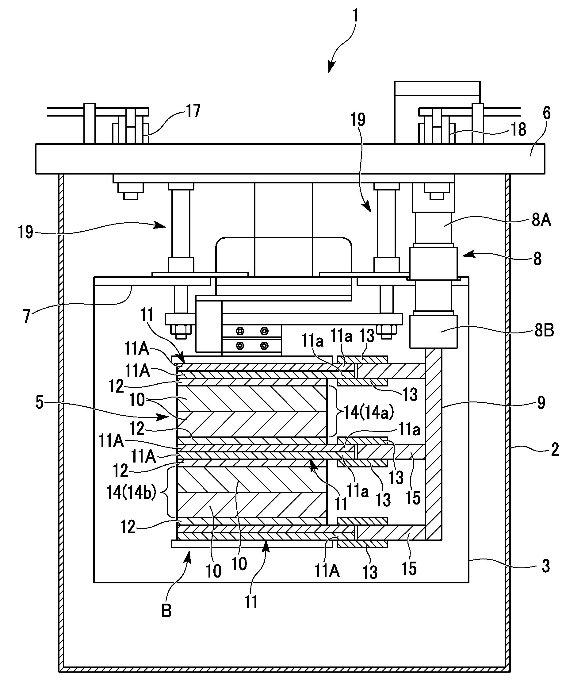
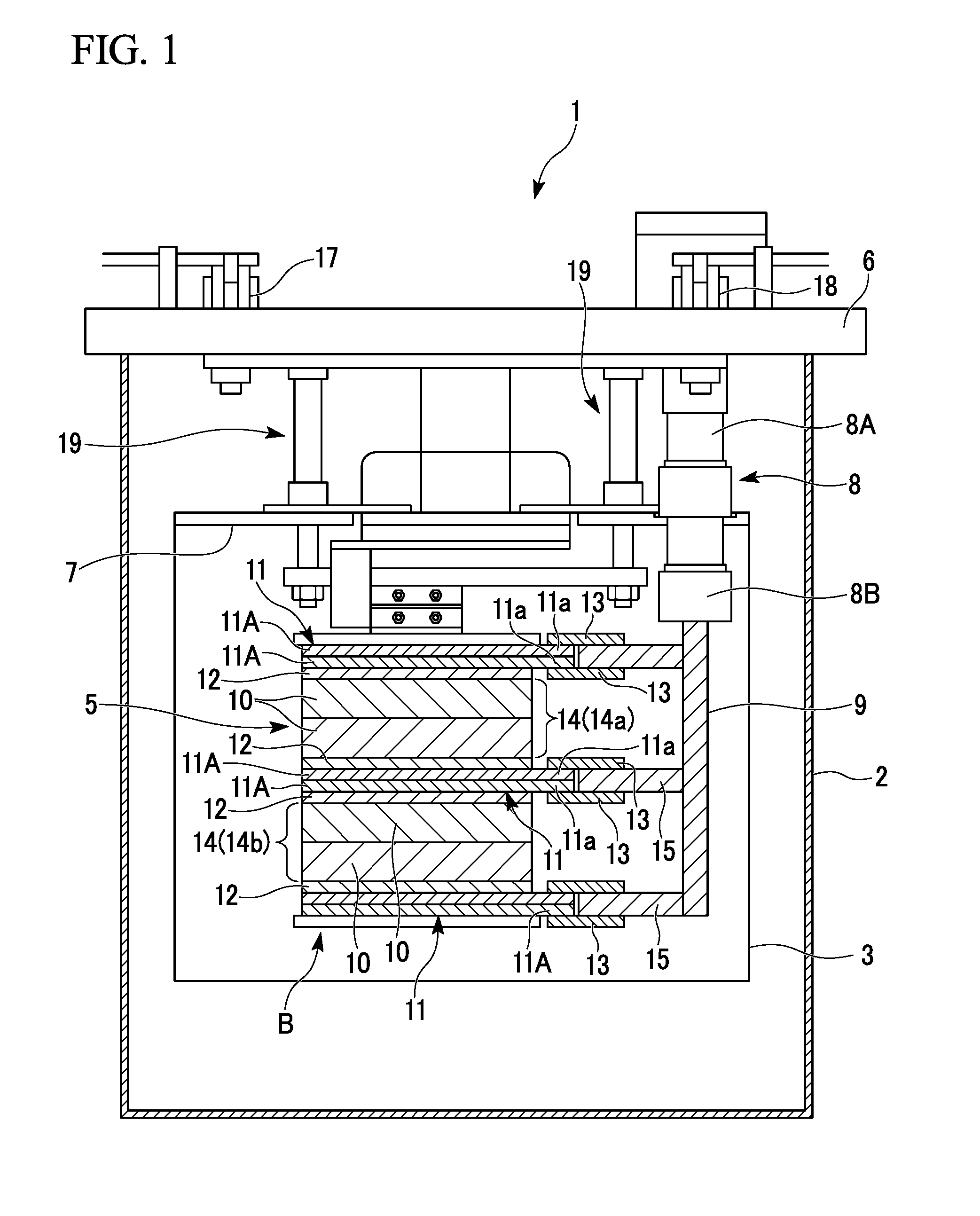
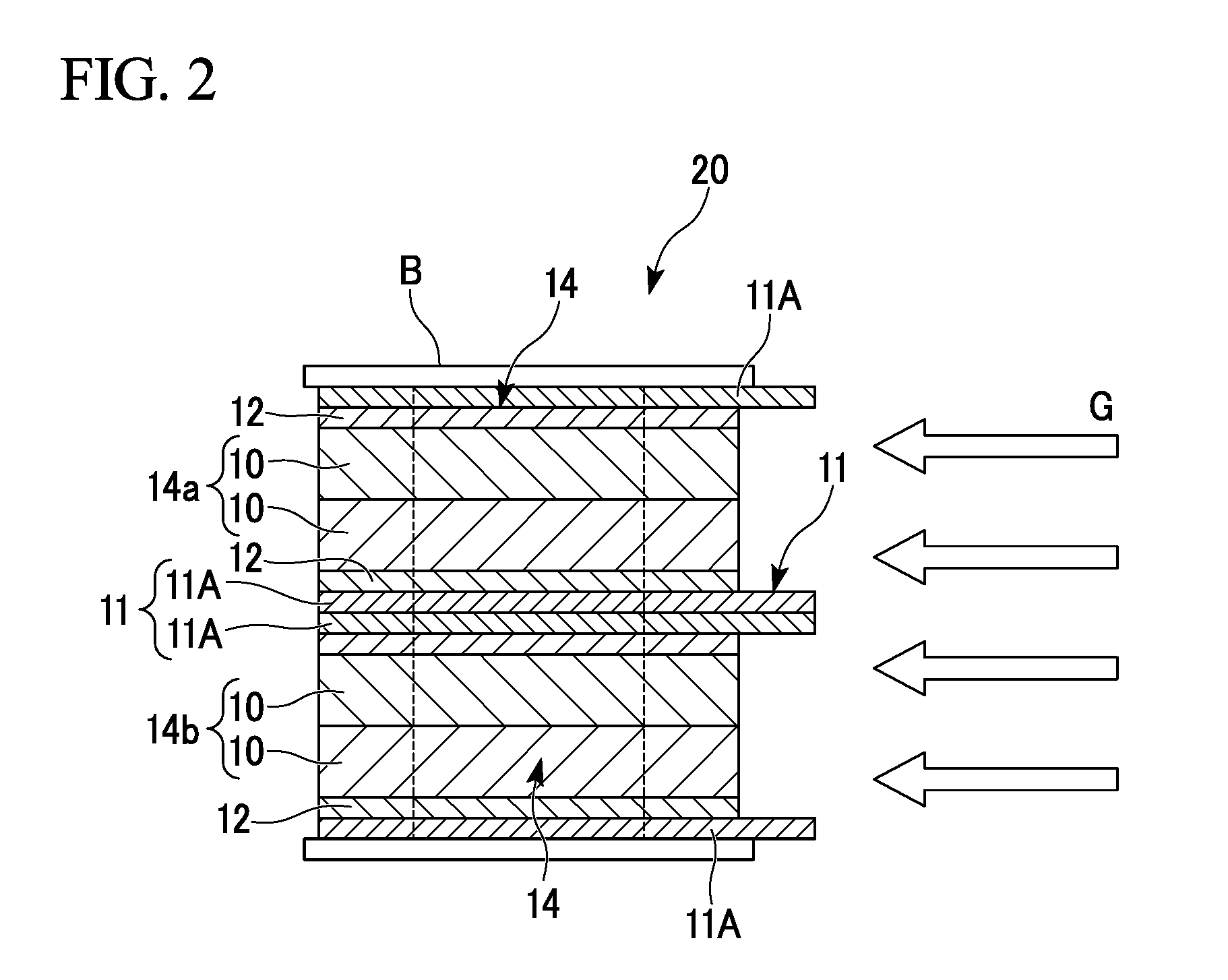
A superconducting coil includes: first and second pancake coils that are formed by winding a superconducting wire, are stacked in a thickness direction, and are adjacent to each other; and a cooling substrate that is provided in contact with an end surface of the first pancake coil and is separable into a plurality of cooling plates.

Description

CROSS REFERENCE TO RELATED APPLICATIONS[0001]This application is a continuation application based on a PCT Patent Application No. PCT / JP2013 / 056129, filed Mar. 6, 2013, whose priority is claimed on Japanese Patent Application No. 2012-049411, filed on Mar. 6, 2012, the entire content of which are hereby incorporated by reference.BACKGROUND OF THE INVENTION[0002]1. Field of the Invention[0003]The present invention relates to a superconducting coil and a superconducting device, and in particular, to a superconducting coil that includes a plurality of laminated pancake coils and is used in a superconducting device, such as a superconducting magnet or a superconducting rotary machine, and a superconducting device including the superconducting coil.[0004]2. Description of the Related Art[0005]In a superconducting device, such as a superconducting magnet or a superconducting motor, a plurality of laminated pancake type superconducting coils may be used. Various structures, such as a stru...

Claims


Application Information

Patent Timeline
Patent Type & Authority Applications(United States)
IPC IPC(8): H01F6/06H01F6/04
CPCH01F6/04H01F6/06H01F5/02
Inventor DAIBO, MASANORI
Owner THE FUJIKURA CABLE WORKS LTD
Learn More