

Vacuum cleaner
- Summary
- Abstract
- Description
- Claims
- Application Information
AI Technical Summary
Benefits of technology
Problems solved by technology
Method used
Image

Examples
Embodiment Construction
[0052]Reference will now be made in detail to one or more embodiments, illustrated in the accompanying drawings, wherein like reference numerals refer to like elements throughout. In this regard, embodiments of the present invention may be embodied in many different forms and should not be construed as being limited to embodiments set forth herein, as various changes, modifications, and equivalents of the systems, apparatuses and / or methods described herein will be understood to be included in the invention by those of ordinary skill in the art after embodiments discussed herein are understood. Accordingly, embodiments are merely described below, by referring to the figures, to explain aspects of the present invention.
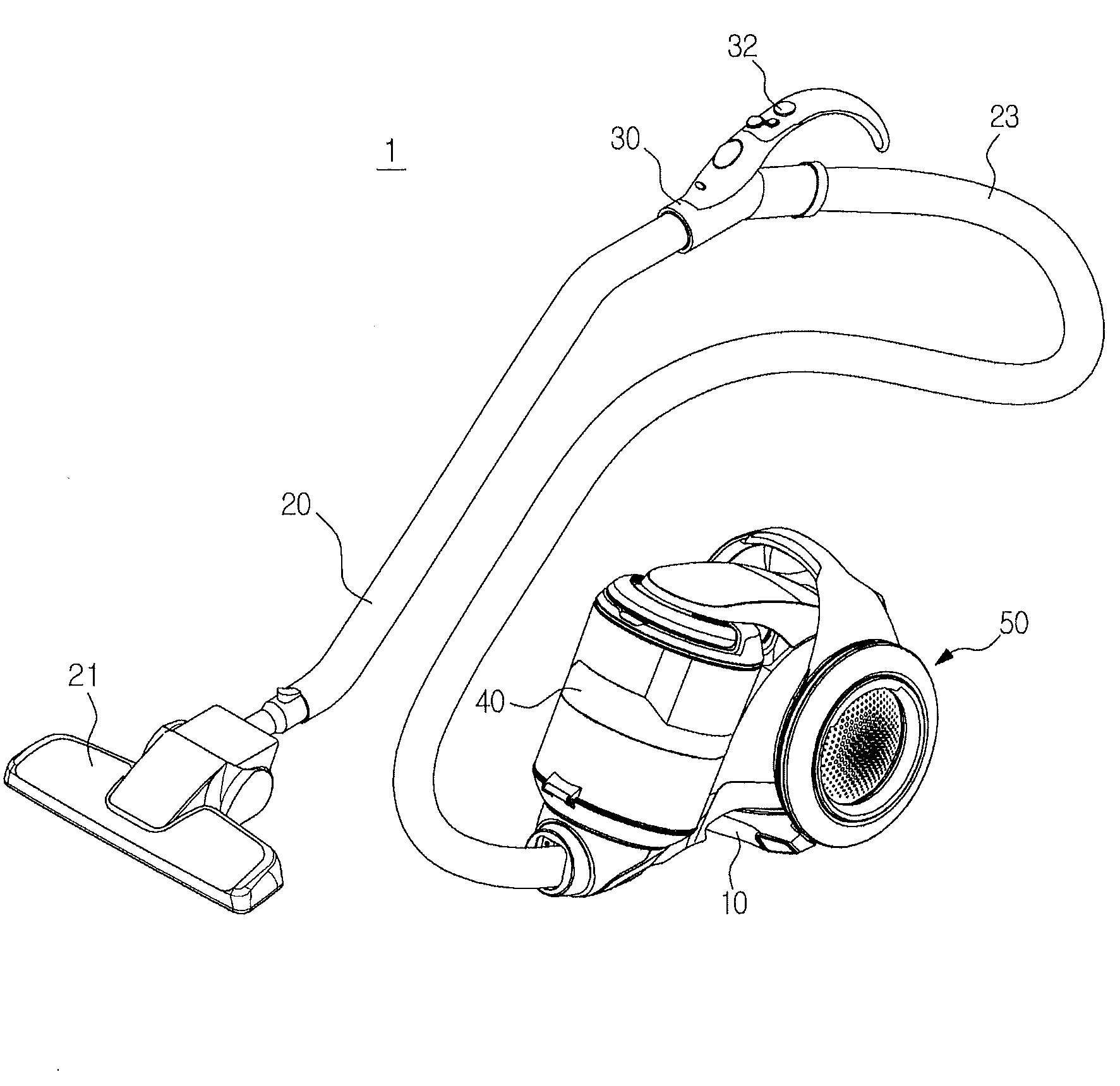
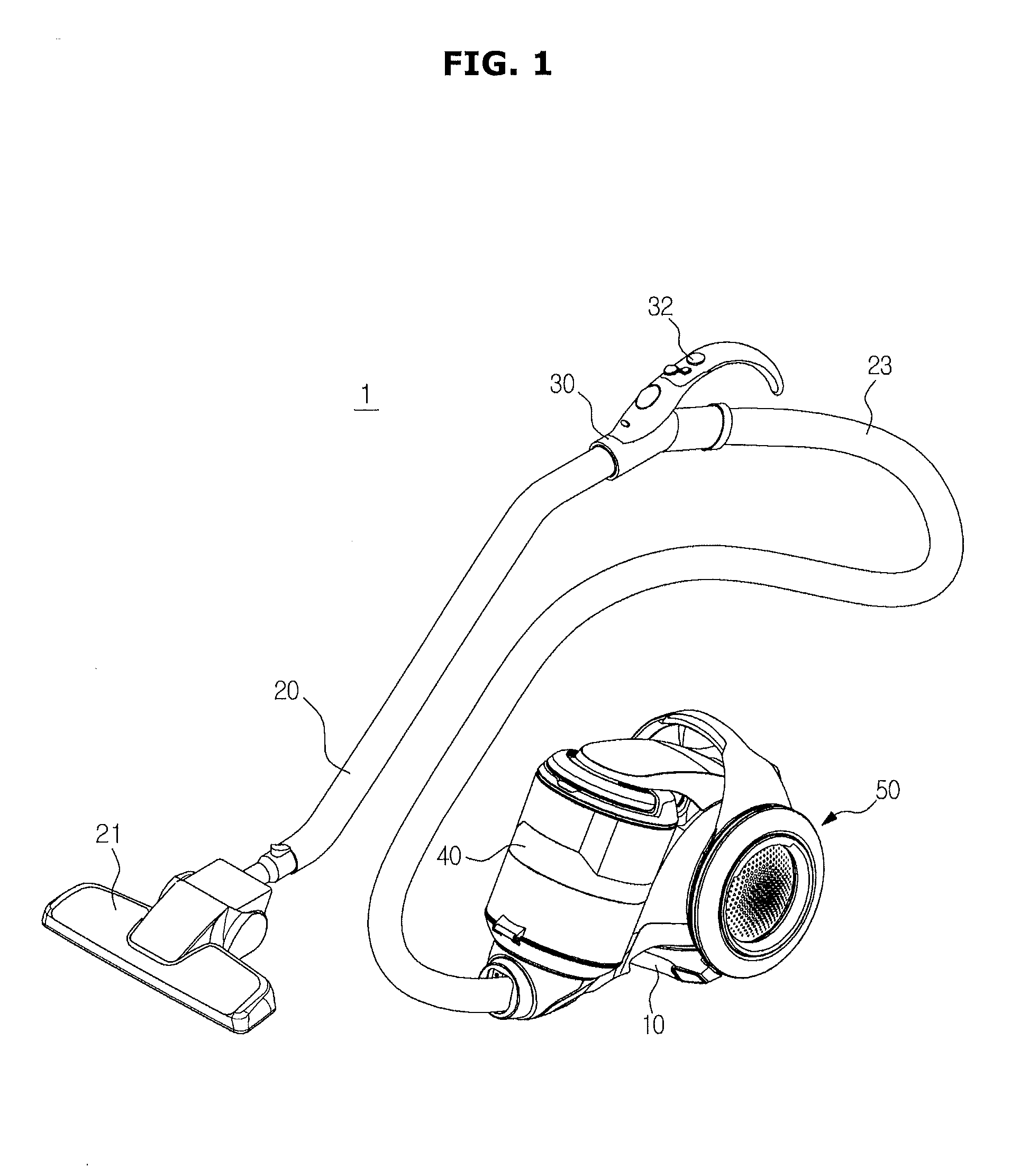
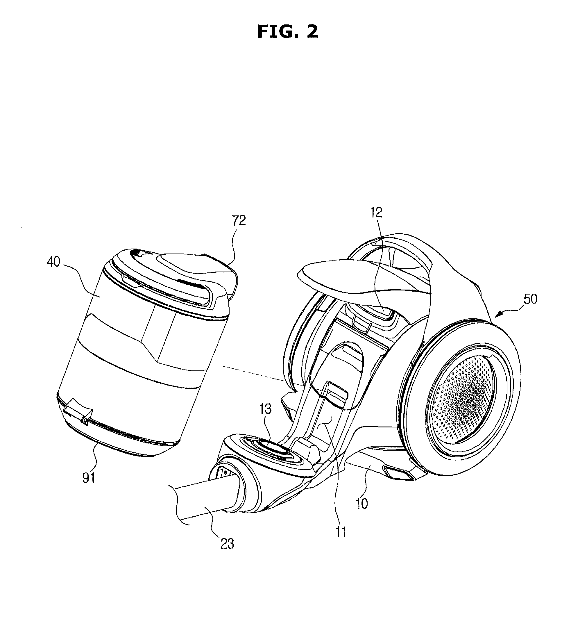
[0053]FIG. 1 is a view showing a vacuum cleaner according to one or more embodiments and FIG. 2 is a view showing a state in which a dust collector is separated from a main body according to one or more embodiments.
[0054]Referring to FIGS. 1 and 2, a vacuum cleaner 1 a...
PUM
 Abstract
Description
Claims
Application Information