Dedicated egr cylinder post combustion injection

a technology of egr cylinder and egr cylinder, which is applied in the direction of combustion engine, charge feed system, non-fuel substance addition to fuel, etc., can solve the problems of reducing the combustion efficiency and/or increasing the smoke conditions during engine operation, and reducing the ability to ignite the charge, so as to reduce the throttling of the engine, reduce the nox emission, and reduce the effect of pumping loss

Active Publication Date: 2014-12-11
FORD GLOBAL TECH LLC
View PDF10 Cites 39 Cited by
  • Summary
  • Abstract
  • Description
  • Claims
  • Application Information

AI Technical Summary

Benefits of technology

[0001]Engines may be configured with exhaust gas recirculation (EGR) systems to divert at least some exhaust gas from an engine exhaust passage to an engine intake passage. By controlling EGR to provide a desired engine dilution, engine pumping work, engine knock, as well as NOx emissions may be reduced. For example, at partial throttle operating conditions, providing EGR to the cylinders of the engine allows for the throttle to be opened to a greater extent for the same engine load. By reducing throttling of the engine, pumping losses may be reduced, thus improving fuel efficiency. Further, by providing EGR to the engine, combustion temperatures may be reduced (especially in implementations where EGR is cooled prior to being provided to the cylinders). Cooler combustion temperatures provide engine knock resistance, and thus increase engine thermal efficiency. Further still, EGR reduces a combustion flame temperature that reduces an amount of NOx generated during combustion.
[0002]In some approaches, gas exhausted from only one or more of a subset of cylinders may be recirculated to provide EGR to all cylinders of the engine. For example, an EGR conduit may be coupled to an exhaust of a dedicated EGR cylinder so that exhaust from the dedicated cylinder is introduced into the intake manifold of the engine to provide EGR. In this way, a substantially fixed amount of EGR flow may be provided to the engine intake.
[0003]In such approaches which use dedicated EGR cylinders to provide EGR to the engine, the inventors herein have recognized that it may be desirable to run the dedicated EGR cylinder rich to increase ignitability of the air, fuel, EGR mixture. The ignitability may be improved due to the presence of hydrogen which is formed in the dedicated cylinder when running rich. Overly increasing the amount of fuel injected into the dedicated cylinder may lead to reduced combustion efficiency and / or increased smoke conditions during engine operation. For example, increasing richness in the EGR cylinder beyond that required for best combustion efficiency may cause smoke formation, and further increasing richness may reduce the ability to ignite the charge. As such, the amount of fuel that can be added to a dedicated EGR cylinder may be limited.
[0005]In this way, an increased amount of fuel may be introduced into the EGR flow while maintaining good combustion with low soot formation. Further, in such an approach, pumping work at part-throttle for the remaining cylinders in the engine may be reduced via fuel evaporation in the dedicated EGR cylinder and fuel injectors in the remaining cylinders may be downsized resulting in cost savings and increased fuel efficiency. Further still, such an approach may be employed during engine cold start conditions while operating the dedicated cylinder in a lean mode when less than full EGR is desired. For example, to help with fuel vaporization, a small amount of fuel could be burned (via a stratified charge injection a during compression stroke of the dedicated EGR cylinder) to heat the air / cylinder and then fuel could be injected later in the cycle to improve evaporation of the fuel. In this way, fuel preparation, e.g., smoke reduction in direct injection applications, during warm-up of the engine may be improved.

Problems solved by technology

Overly increasing the amount of fuel injected into the dedicated cylinder may lead to reduced combustion efficiency and / or increased smoke conditions during engine operation.
For example, increasing richness in the EGR cylinder beyond that required for best combustion efficiency may cause smoke formation, and further increasing richness may reduce the ability to ignite the charge.
As such, the amount of fuel that can be added to a dedicated EGR cylinder may be limited.

Method used


Image

  • Dedicated egr cylinder post combustion injection
  • Dedicated egr cylinder post combustion injection
  • Dedicated egr cylinder post combustion injection

Examples


Embodiment Construction

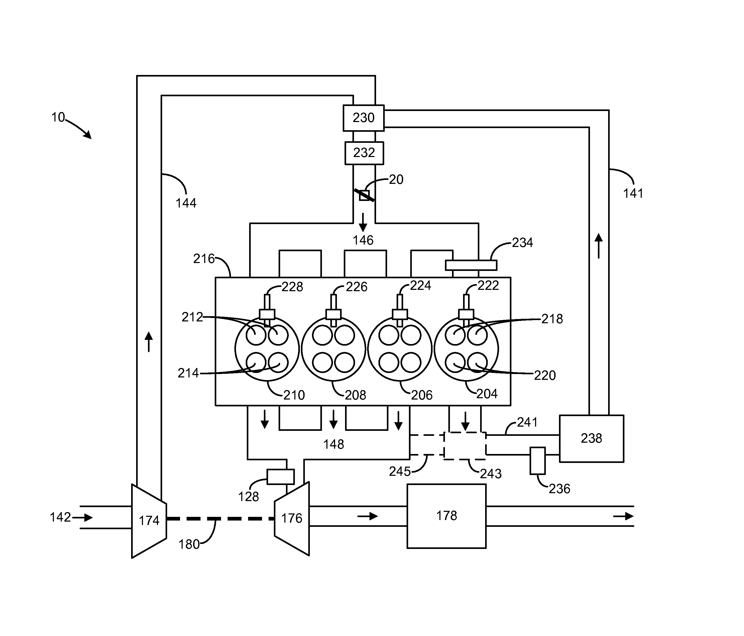
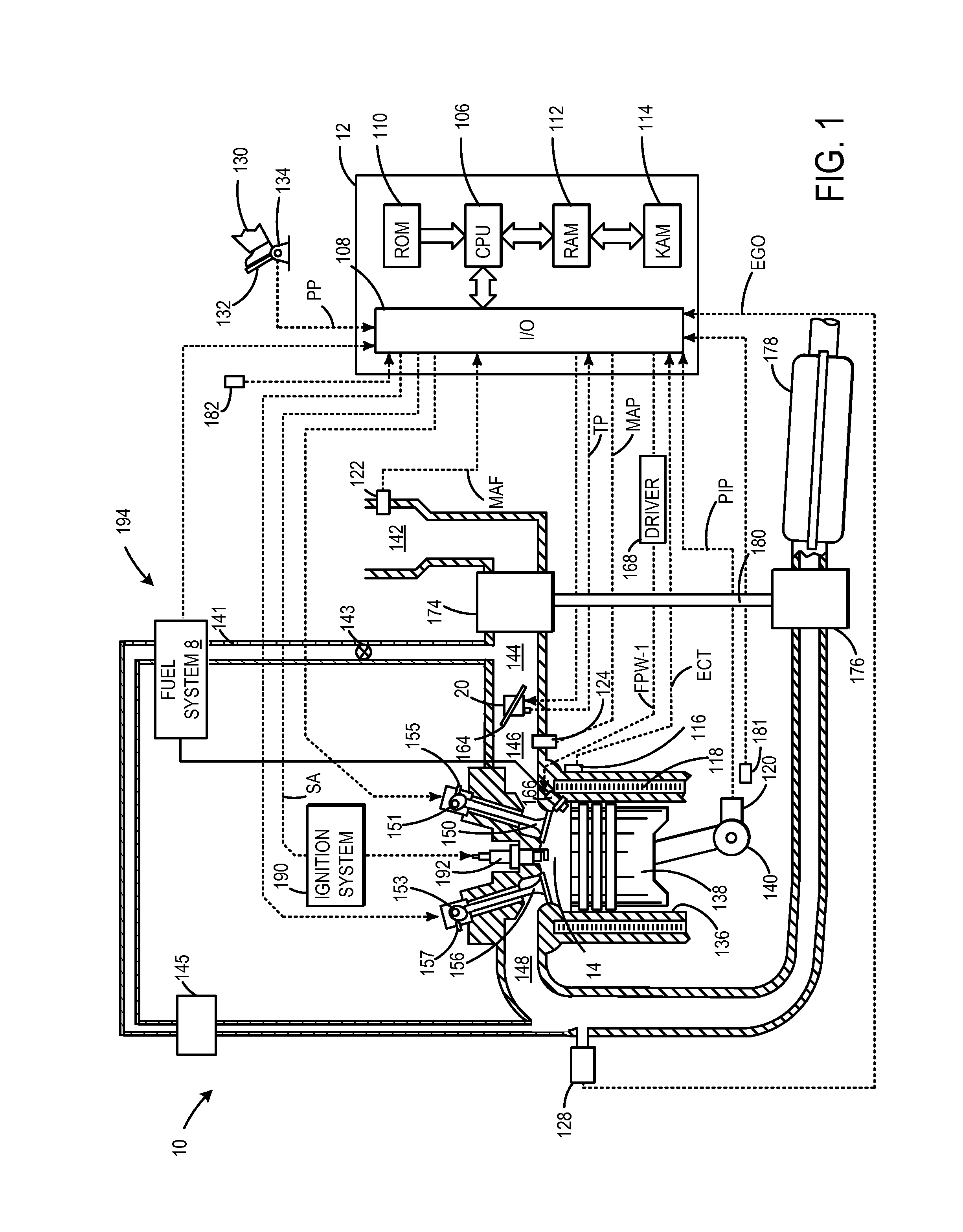
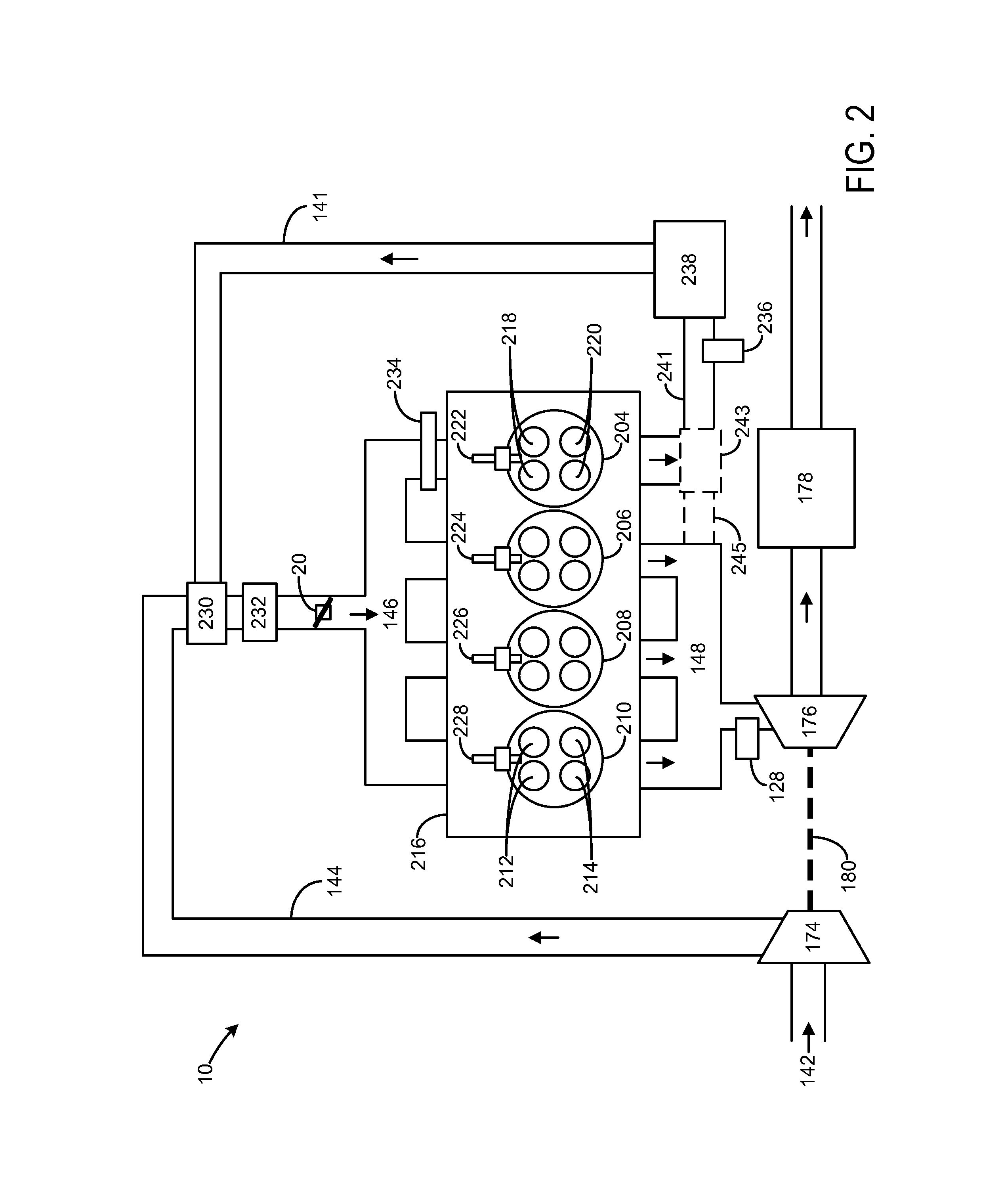
[0010]The present description is related to increasing an amount of fuel in an exhaust gas recirculation (EGR) flow in an engine, such as the engine system shown in FIG. 1. As shown in FIG. 2, an engine system may include a dedicated or donor cylinder from which EGR flow is drawn. For example, an exhaust of a dedicated EGR cylinder may be coupled to an intake of the engine to provide exhaust gas from the dedicated cylinder to all of the cylinders in the engine. As remarked above, it may be desirable to increase the richness in the dedicated EGR cylinder to increase ignitability of the mixture in each cylinder which includes this EGR However, increasing the amount of fuel injected into the dedicated cylinder may lead to reduced combustion efficiency and increased smoke or soot conditions during engine operation. For example, increasing richness in the EGR cylinder beyond that required for best combustion efficiency may cause smoke formation, and further increasing richness may reduce...


PUM


Abstract

Systems and methods for increasing an amount of fuel injected into a dedicated exhaust gas recirculation (EGR) cylinder in an engine are disclosed. In one example approach, a method comprises, prior to combustion, injecting a first amount of fuel to a dedicated EGR cylinder, and after combustion and during an expansion and / or exhaust stroke, directly injecting a second amount of fuel to the dedicated EGR cylinder.

Description

BACKGROUND AND SUMMARY[0001]Engines may be configured with exhaust gas recirculation (EGR) systems to divert at least some exhaust gas from an engine exhaust passage to an engine intake passage. By controlling EGR to provide a desired engine dilution, engine pumping work, engine knock, as well as NOx emissions may be reduced. For example, at partial throttle operating conditions, providing EGR to the cylinders of the engine allows for the throttle to be opened to a greater extent for the same engine load. By reducing throttling of the engine, pumping losses may be reduced, thus improving fuel efficiency. Further, by providing EGR to the engine, combustion temperatures may be reduced (especially in implementations where EGR is cooled prior to being provided to the cylinders). Cooler combustion temperatures provide engine knock resistance, and thus increase engine thermal efficiency. Further still, EGR reduces a combustion flame temperature that reduces an amount of NOx generated duri...

Claims


Application Information

Patent Timeline
Patent Type & Authority Applications(United States)
IPC IPC(8): F02M25/07F02D19/12
CPCF02D19/12F02M25/07F02M26/05F02M26/43F02M26/02
Inventor ULREY, JOSEPH NORMANERVIN, JAMES DOUGLASBOYER, BRAD ALANSTYLES, DANIEL JOSEPHMCCONVILLE, GREGORY PATRICKKU, KIM HWE
Owner FORD GLOBAL TECH LLC
Why Eureka
Try Eureka