Overhead antenna live inventory locating system

a technology of inventory locating and overhead antenna, applied in the field of inventory systems and methods, can solve the problems of impede the operation of the store, the method of inventorying electronic tags has a margin of error, and the rfid reader can miss, so as to reduce the effect of reducing the distance to the antenna and less effectiv

Inactive Publication Date: 2014-12-11
RFID RESOLUTION TEAM
View PDF5 Cites 79 Cited by
  • Summary
  • Abstract
  • Description
  • Claims
  • Application Information

AI Technical Summary

Benefits of technology

[0009]Automated systems for detecting electronic inventory tags can be used to provide consistent results and near real-time inventory information. Automated systems can utilize arrays of overhead readers and exciters, arrays of overhead bidirectional phased array systems and / or smart shelving and smart hanging rails. These automated systems can, to varying degrees, give the location of any given item in the store.
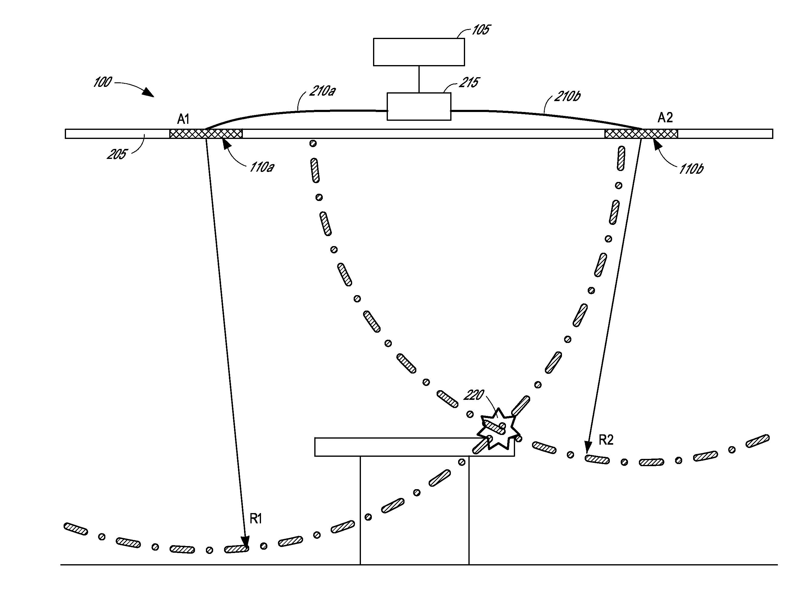
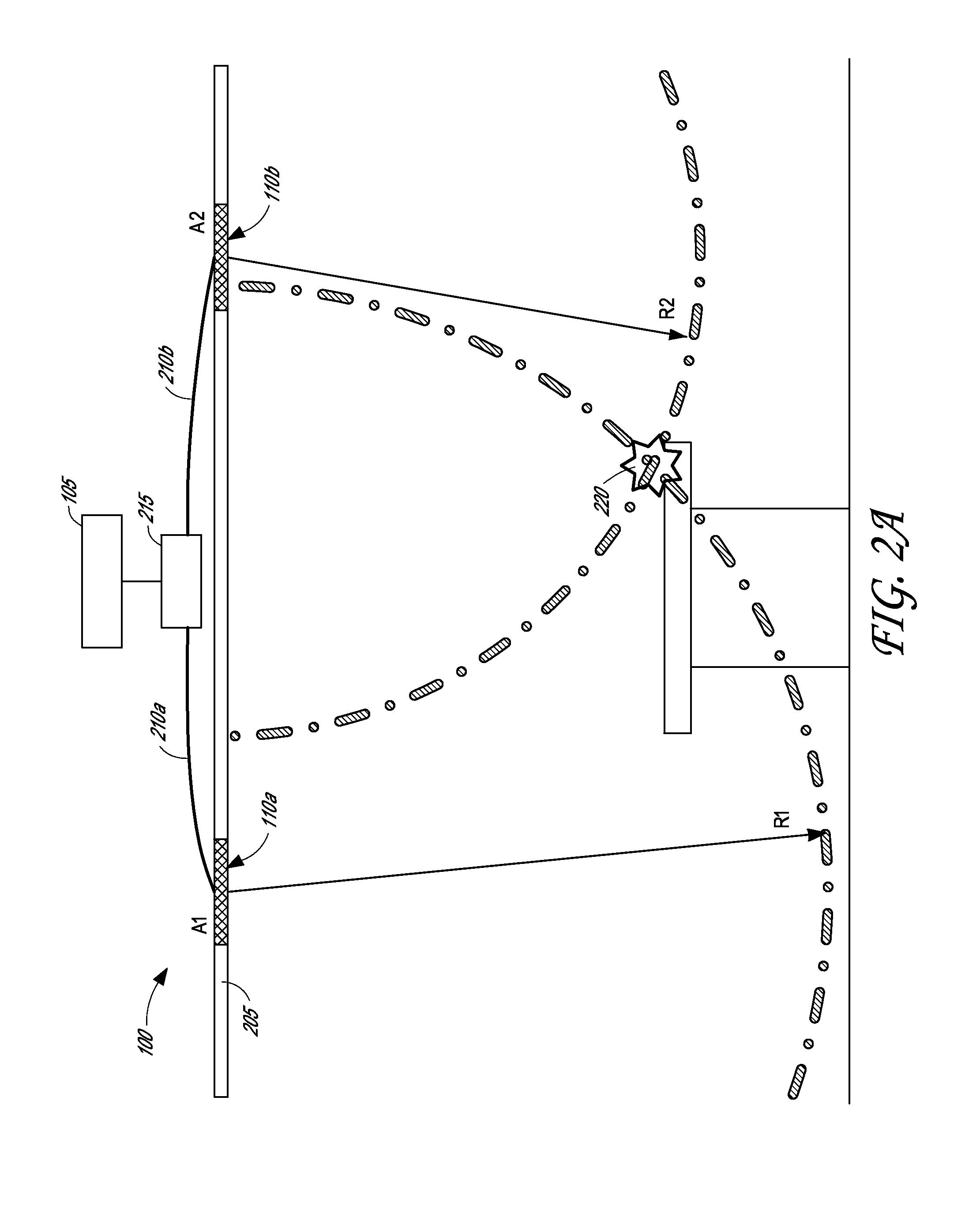
[0012]Some overhead inventory systems can be less effective when installed in a ceiling because they require a minimum height in order to operate effectively. For example, some antennas require structures that are too big to fit above a ceiling and would impede the operation of the store if mounted on the ceiling but facing toward the ground. As another example, some systems that use phased arrays can require about ten feet for the wave front to form before being able to reliably detect an RFID tag. Moreover, some phased arrays can have an antenna beam angle that defines a cone that covers a smaller and smaller area as the distance to the antenna decreases. In stores with low ceilings or where inventory is located close to the ceiling, this may exclude many items from the field of view of the antenna, and other antennas may be required to obtain complete coverage thereby increasing the cost of the system. Although some of these issues can be mitigated by a carefully designed installation or by adding more antennas to the automated reading system, these solutions can further increase the cost of these systems.
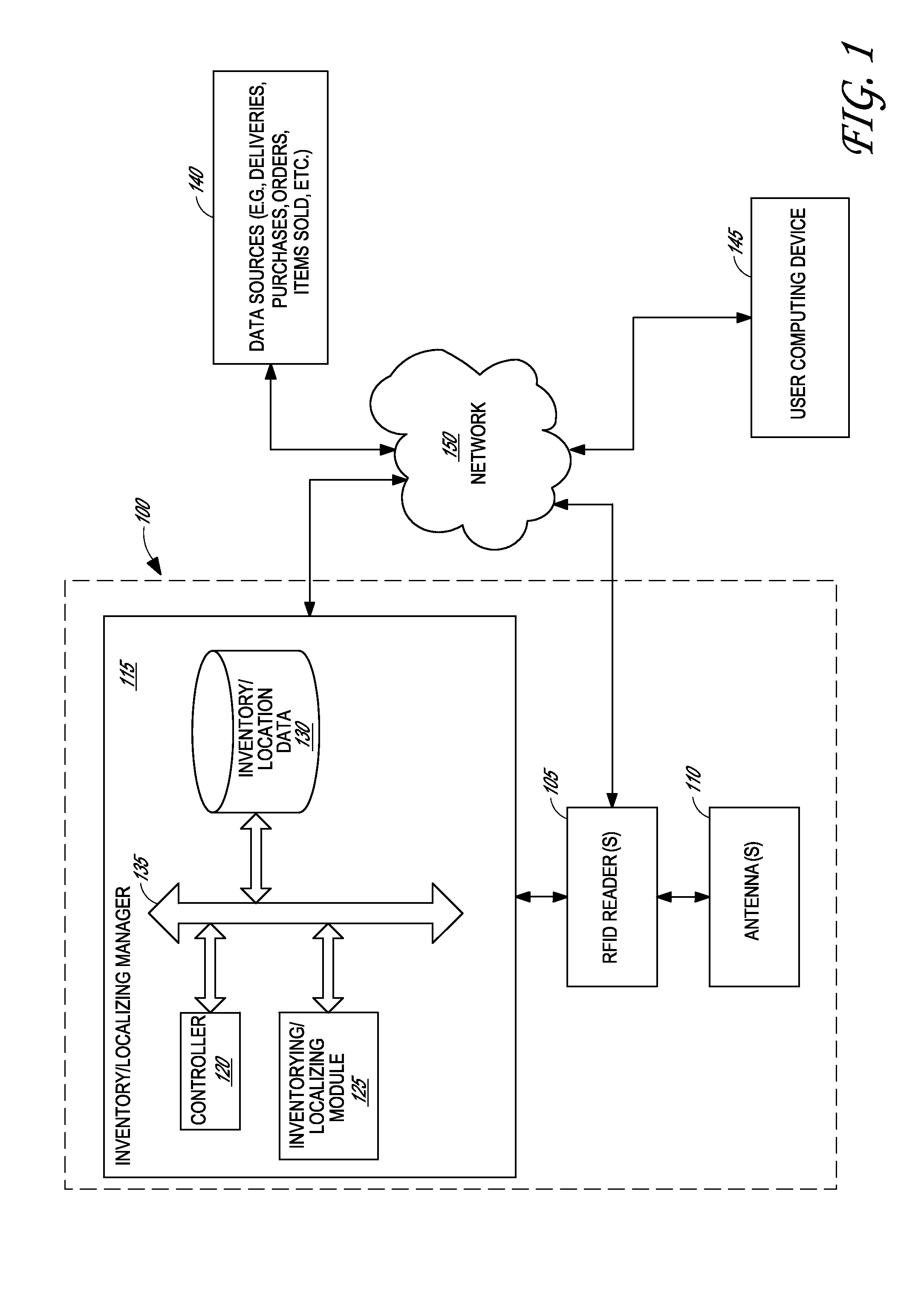
[0013]Therefore, in some embodiments a low-cost automated inventory and localizing system can provide acceptable effectiveness, provide real-time inventory and location information, and resist interference with normal store operations. In some implementations, an overhead antenna inventory / locating system can include a plurality of antennas mounted in an elevated support structure. The antennas can be coupled to RFID readers that interrogate electronic tags. The inventory system can analyze the information received from the detected electronic tags and produce inventory data and location information for the tags. The antennas can be patch antennas mounted in or near a ceiling (such as in or on ceiling tiles). In some embodiments, the antennas can be configured to provide broad coverage from a relatively low ceiling height, are relatively low-cost, and can be configured in such a way as to provide accurate location information for detected tags. The inventory system can be configured to provide near real-time inventory and location information.
[0014]In some embodiments, the electronic tags are passive RFID tags. Passive RFID tags can be more cost effective than tags that utilize batteries or other power sources, such as active RFID tags. In general, a passive RFID tag is cheaper than a corresponding active RFID tag and may require less maintenance. Configuring the overhead antenna system to function with passive RFID tags can reduce the overall cost of implementing the system where passive RFID tags are currently being used. Thus, providing real-time inventory and location information for passive RFID tags can be a cost-effective and practical solution to inventory and locating needs.

Problems solved by technology

A common challenge in many businesses is keeping track of inventory.
This challenge is especially intense when there is high product volume, a diverse product line, and multiple sources of product movement or inventory change.
However, this method of inventorying electronic tags has a margin of error due to the manual nature of the operation.
For example, a worker moving through a storage facility with an RFID reader can miss inventorying particular areas due to mistake, becoming distracted during the operation, forgetting about areas, or rushing to finish the operation.
In addition, a worker performing an inventory operation in this manner does not record the location of the items.
Moreover, manual inventorying of electronic tags does not provide a real-time inventory of the store and can be an inefficient use of time, money, and resources.
Finally, manually inventorying a store in this fashion may interfere with the normal course of operations of the store or warehouse.
However, some overhead automated systems may cost significantly more than a handheld reader and a full time clerk even for comparatively small facilities.
Some types of automated systems do not scale well, with costs climbing rapidly as the store size and population of items grows.
Some automated systems can also require considerable setup and infrastructure to install, which is expensive, and can conflict with the store's decor.
In some cases the system may need to be re-installed or calibrated if the store display scheme is changed significantly, once again increasing the cost to run and maintain the system.
Inventory systems that include overhead antennas and readers to read RFID tags may not provide location information beyond a determination that the item is located within a predefined zone.
In systems that utilize a single antenna to cover a particular area of a store, the location information is limited to determining the presence of the tagged article in that area.
Additionally, if the tag is shielded from the reader's transmitted signal, the tag may not be read at all.
However, there may be ambiguity as to whether the article entered or exited the monitored choke point.
Moreover, choke points do not provide real-time location information, but instead imply a location based on the direction of motion of the tag and the time the tag passed the choke point.
Some overhead inventory systems can be less effective when installed in a ceiling because they require a minimum height in order to operate effectively.
For example, some antennas require structures that are too big to fit above a ceiling and would impede the operation of the store if mounted on the ceiling but facing toward the ground.
In stores with low ceilings or where inventory is located close to the ceiling, this may exclude many items from the field of view of the antenna, and other antennas may be required to obtain complete coverage thereby increasing the cost of the system.
Although some of these issues can be mitigated by a carefully designed installation or by adding more antennas to the automated reading system, these solutions can further increase the cost of these systems.

Method used


Image

  • Overhead antenna live inventory locating system
  • Overhead antenna live inventory locating system
  • Overhead antenna live inventory locating system

Examples


example patch

Antenna Mounted in a Ceiling Tile

[0084]FIG. 7 illustrates an example of a patch antenna 700 mounted to a ceiling tile 710 according to some embodiments. The patch antenna 700 comprises a patch antenna housing 705 that can be mounted to a ceiling tile 710. The patch antenna 700 can be part of an overhead antenna inventory / locating system as described herein above. The patch antenna 700 can be coupled to an RFID reader through cable 720. The cable 720 can be configured to provide electromagnetic signals sufficient to drive the antenna 700 at the desired frequency, power, and polarization. The cable 720 can be configured to convey signals to the RFID reader from the antenna 700.

[0085]The patch antenna 705 can be mounted to the ceiling tile 710, for example, using mounting interfaces 715. In some embodiments, the patch antenna housing 705 can be mounted to the ceiling tile 710 using a permanent connection such as, for example, adhesives, thermal bonding, welding, clamps, friction, faste...


PUM

PropertyMeasurementUnit
frequencyaaaaaaaaaa
frequencyaaaaaaaaaa
frequencyaaaaaaaaaa

Abstract

Overhead antenna live inventory locating systems and methods are provided. The overhead antenna inventory / locating system can include a plurality of antennas mounted in an elevated support structure. The antennas can be coupled to RFID readers that interrogate electronic tags. The inventory system can analyze the information received from the detected electronic tags and produce inventory data and location information for the tags. The antennas can be patch antennas mounted to ceiling tiles such that they can be positioned in the ceiling of a facility. The antennas can be configured to provide broad coverage from a relatively low ceiling height. The low-cost antennas can be configured in such a way as to provide accurate location information for detected tags. The inventory system can be configured to provide near real-time inventory and location information.

Description

CROSS-REFERENCE TO RELATED APPLICATIONS[0001]This application is a continuation of Patent Cooperation Treaty Application No. PCT / US2013 / 026835, filed Feb. 20, 2013, entitled “OVERHEAD ANTENNA LIVE INVENTORY LOCATING SYSTEM,” which claims the benefit of priority under 35 U.S.C. §119(e) of U.S. Provisional Patent Application 61 / 601,976, filed Feb. 22, 2012, entitled “OVERHEAD ANTENNA LIVE INVENTORY LOCATING SYSTEM,” the entire contents of both of which are hereby incorporated by reference herein and made a part of this specification for all that they disclose.BACKGROUND[0002]1. Field[0003]The disclosure relates generally to inventory systems and methods, and more particularly to inventory systems and methods for reading electronic tags.[0004]2. Description of Related Art[0005]A common challenge in many businesses is keeping track of inventory. This challenge is especially intense when there is high product volume, a diverse product line, and multiple sources of product movement or inv...

Claims


Application Information

Patent Timeline
Patent Type & Authority Applications(United States)
IPC IPC(8): G06K7/10G06Q10/08
CPCG06Q10/087G06K7/10475G06K7/10356Y10T29/49018
Inventor DAVIDSON, WILLIAM EDWARD
Owner RFID RESOLUTION TEAM
Why Eureka
Try Eureka