
System and Method for Reading Code Symbols at Long Range Using Source Power Control

a technology of source power control and code symbols, applied in the field of reading code symbols, can solve the problems of weaker laser light signal, limited ability of gain control techniques to achieve greater dynamic range, and difficulty in obtaining readings from barcodes located at these greater distances from barcode scanners

Active Publication Date: 2014-12-11
HAND HELD PRODS
View PDF1 Cites 574 Cited by
  • Summary
  • Abstract
  • Description
  • Claims
  • Application Information

AI Technical Summary

Benefits of technology

The present patent text describes a system and method for reading code symbols using a laser scanning module. The system uses an automatic gain control circuit or microprocessor to control the power supply to maintain the intensity of the reflected light within a predetermined range. The method includes supplying power to a laser source to generate a laser beam, scanning the beam across a laser scanning field, and detecting the intensity of the reflected light. A signal is generated based on the detected intensity, and the power supply is controlled in response to the signal. The technical effects include efficient and accurate code symbol reading at longer ranges using a laser scanning module.

Problems solved by technology

Attempting to gather readings from a barcode located at these greater distances from the barcode scanner presents significant challenges.
In particular, the further away that the barcode is from the barcode scanner, the weaker the return laser light signal will be at the time of signal detection at the photodetector.
The ability of these techniques of applying gain control to the received signal to achieve greater dynamic range is limited, for example, by the existence of laser noise.
Increasing the gain of the received signal also results in proportional increases to signal noise (e.g., laser noise), which can significantly interfere with the ability to decode the scanned barcode.

Method used


Image

  • System and Method for Reading Code Symbols at Long Range Using Source Power Control
  • System and Method for Reading Code Symbols at Long Range Using Source Power Control
  • System and Method for Reading Code Symbols at Long Range Using Source Power Control

Examples


Embodiment Construction

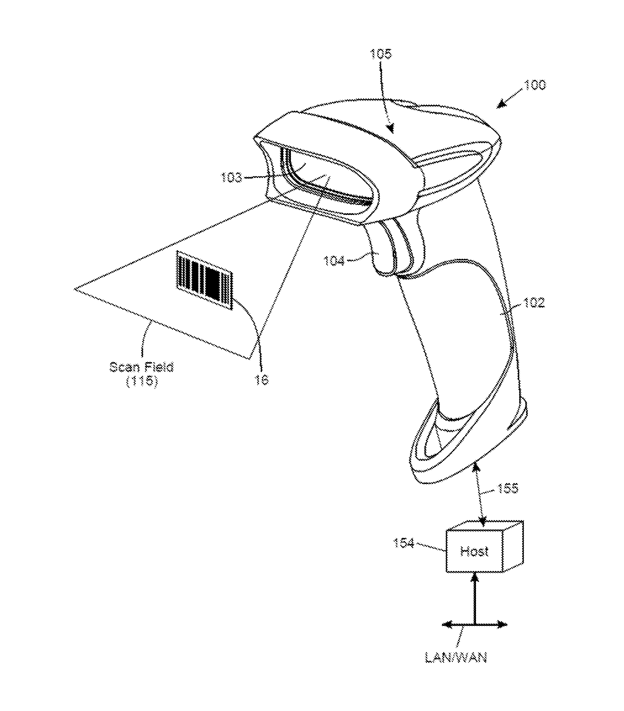
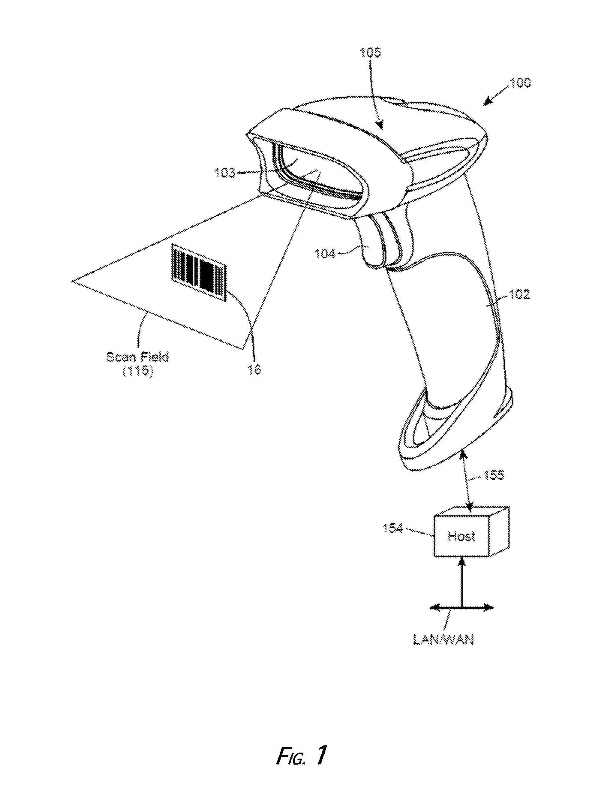
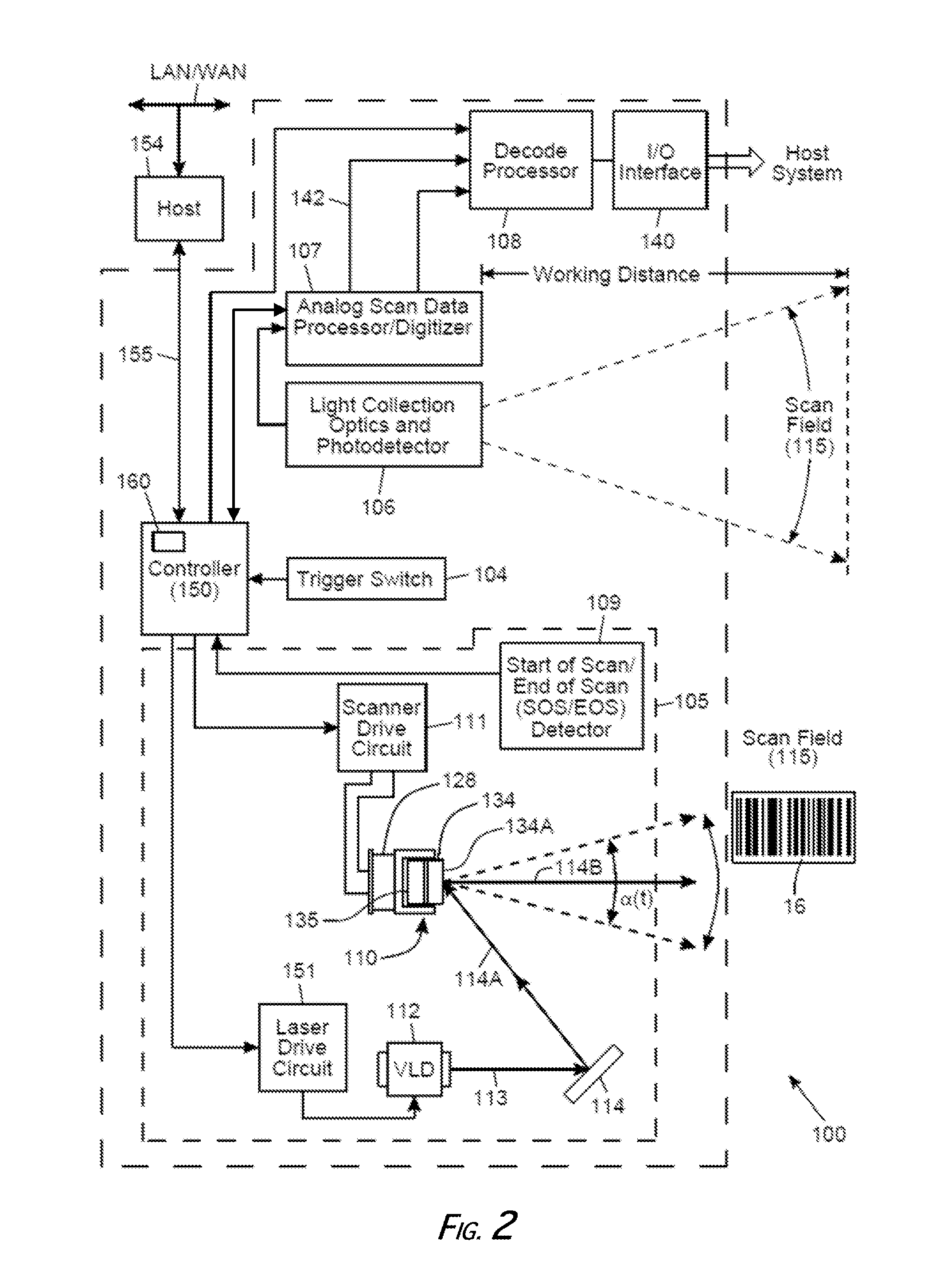
[0016]Referring to the figures in the accompanying drawings, the illustrative embodiments of the code symbol reading system according to the present invention will be described in great detail, where like elements will be indicated using like reference numerals. Turning now to the drawings, FIGS. 1 and 2 depict an exemplary code symbol reading system according to the present invention. The code symbol reading system 100 has a housing 102 having a head portion and a handle portion supporting the head portion. A light transmission window 103 is integrated with the head portion of the housing 102. A trigger switch 104 is integrated with the handle portion of the housing 102. The trigger switch 104 is for generating a trigger event signal to activate a scanning module 105. The scanning module 105 repeatedly scans across its scanning field 115 a light beam (e.g., a visible laser beam) generated by light source 112 (e.g., a laser source). The laser source 112 has optics to produce a laser...


PUM


Abstract

A system and method are presented for improving the performance of code scanners in the extended and far ranges. At these distances, the intensity of the laser beam reflected off the code symbol can be markedly decreased, thereby decreasing the likelihood of a successful reading of the code symbol by the code scanner. The system provides for dynamic power increases to the laser source to generate a greater dynamic range.

Description

FIELD OF THE INVENTION[0001]The disclosure relates generally to improvements in reading code symbols, and more particularly, to a system and method for reading code symbols at long range using source power control.BACKGROUND OF THE DISCLOSURE[0002]A code symbol reading device (e.g., barcode scanner, barcode reader, RFID reader) is a specialized input device for certain data systems commonly used by retailers, industrial businesses, and other businesses having a need to manage large amounts of inventory. Code symbol reading devices are often employed to read barcodes. A barcode is a machine-readable representation of information in a graphic format. The most familiar of these graphic symbols is a series of parallel bars and spaces of varying widths, which format gave rise to the term “barcode.” The adoption of the Universal Product Code (UPC) version of barcode technology 1973 quickly led to a revolution in logistics by obviating the need for manual retry of long number strings.[0003...

Claims


Application Information

Patent Timeline
IPC IPC(8): G06K7/10
CPCG06K7/10821G06K7/10584
Inventor XIAN, TAOGERMAINE, GENNADYWANG, YNJIUN PAULCOLAVITO, STEPHENVAN HORN, ERIK
Owner HAND HELD PRODS
Learn More