Non-contact power supply system
- Summary
- Abstract
- Description
- Claims
- Application Information
AI Technical Summary
Benefits of technology
Problems solved by technology
Method used
Image

Examples
first embodiment
[0045]A first embodiment of a contactless power supply according to the present invention will now be described with reference to FIGS. 1 to 6.
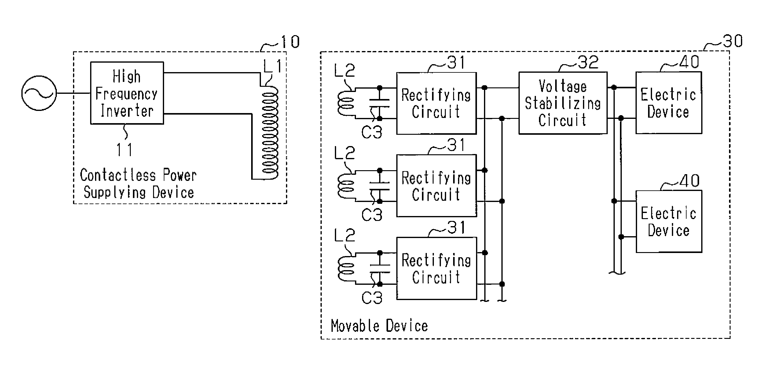
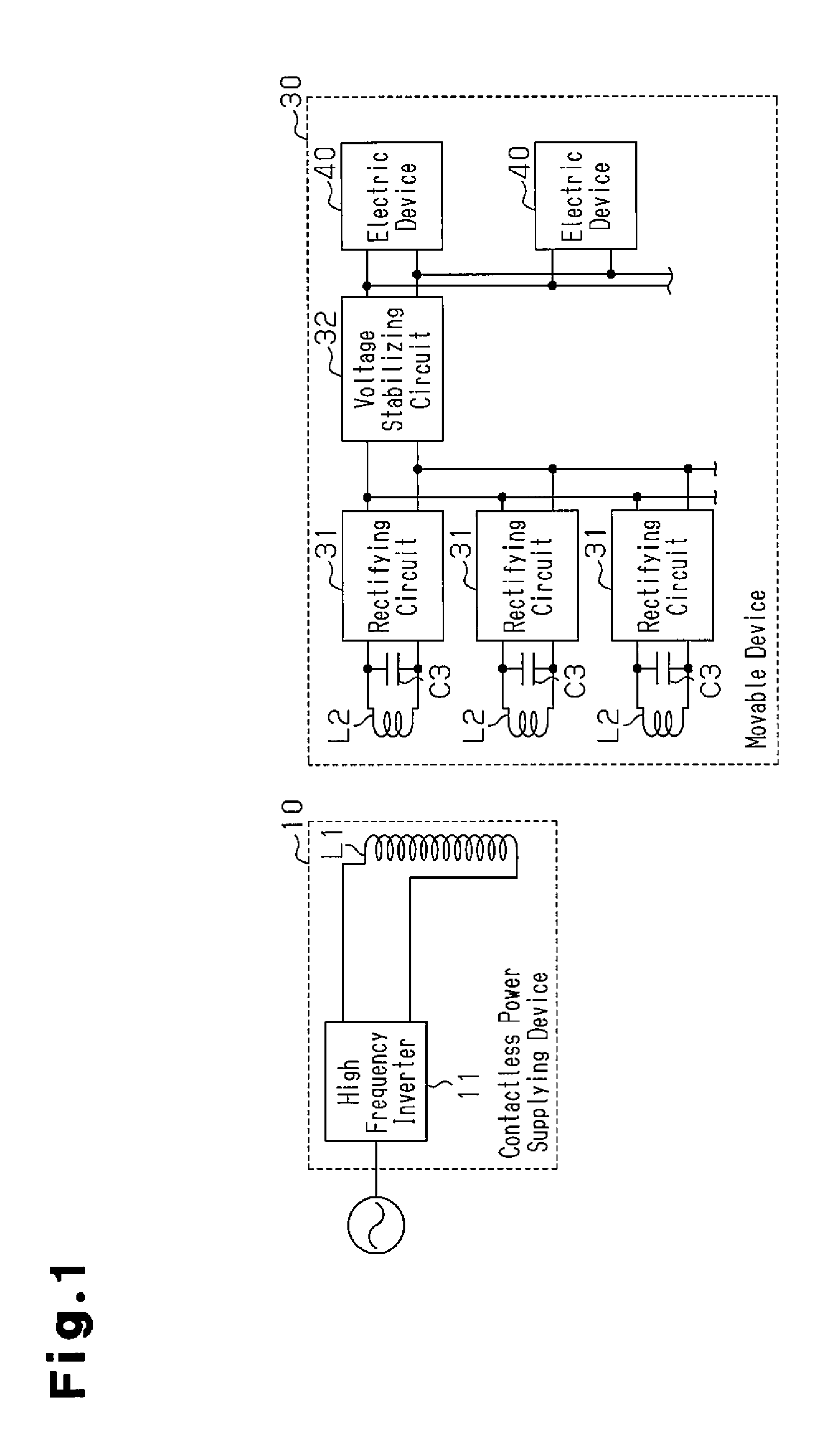
[0046]As shown in FIG. 1, the contactless power supply system includes a power supplying device 10 and a movable device 30. The electrical configuration of the contactless power supplying device 10 and the movable device 30 will now be described.
[0047]Power Supplying Device
[0048]The contactless power supplying device 10 includes a high frequency inverter 11 and a primary coil L1.
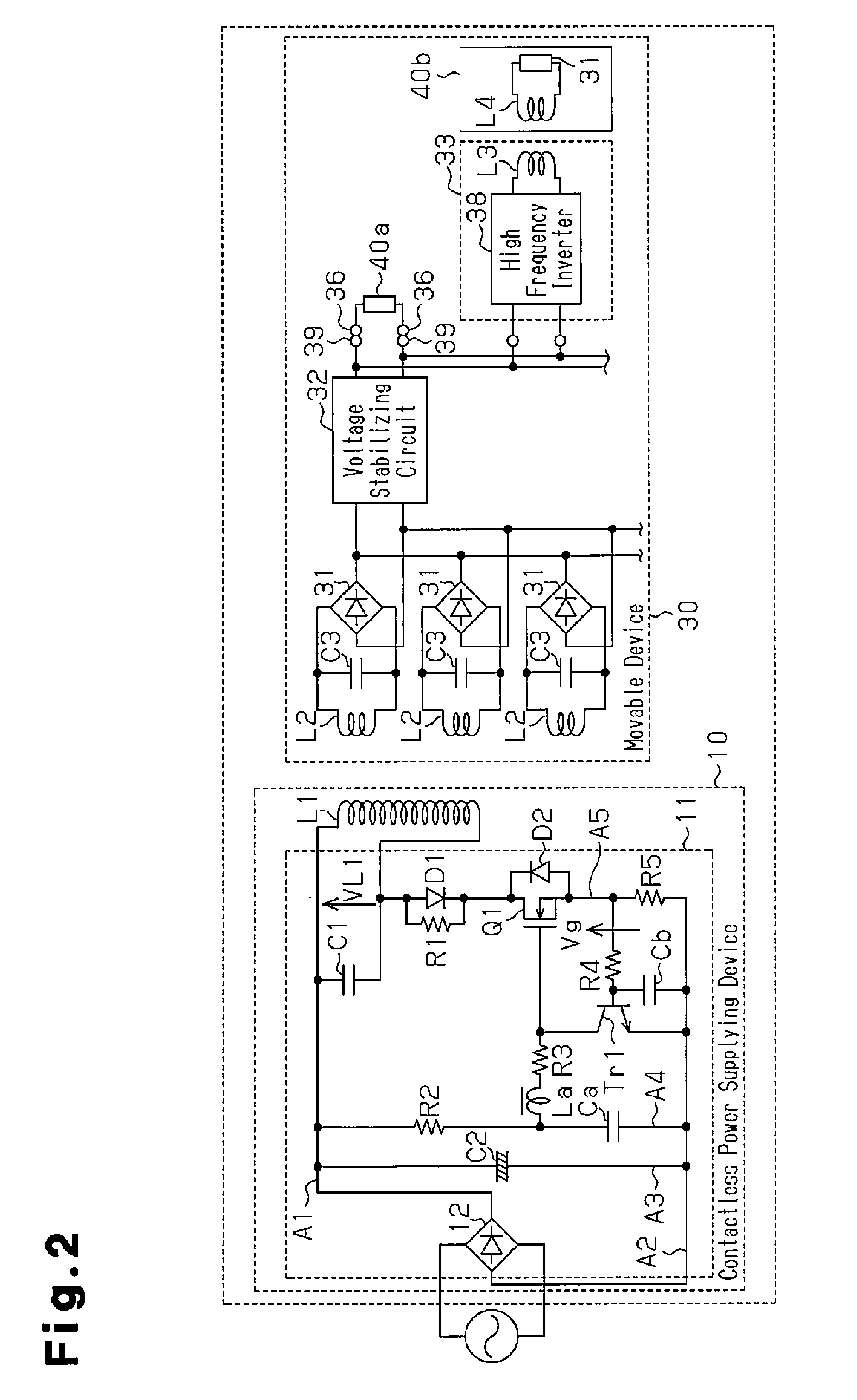
[0049]The high frequency inverter 11 converts the power from a commercial power supply to high frequency current, and supplies the high frequency current to the primary coil L1. In detail, as shown in FIG. 2, the high frequency inverter 11 is formed by a single-transistor voltage resonance type inverter.
[0050]More specifically, the high frequency inverter 11 includes a primary side parallel resonance capacitor C1, a smoothing capacitor C2, a full-wave rectifying circu...
second embodiment
[0102]A second embodiment of the present invention will now be described with reference to FIG. 7. The contactless power supply system of the present embodiment is substantially similar to the first embodiment except in that the movable device is a cart and that the location of the power supplying device differs from the first embodiment. The description hereafter will focus on differences from the first embodiment.
[0103]As shown in FIG. 7A, the movable device 50 is configured as a cart including a box-shaped base 51 and four wheels 52 coupled to the lower surface of the base 51. Secondary coils L2 are arranged in the longitudinal direction in the rear surface of the base 51.
[0104]As shown in FIGS. 7B and 7C, an electric device 40 such as a TV, an iron, and the like is set on the upper surface of the base 51. In the same manner as the first embodiment, power may be supplied from the movable device 50 to the electric device 40 through a configuration in which the plug of the electric...
third embodiment
[0111]A third embodiment of the present invention will now be described with reference to FIG. 8. The contactless power supply system of the present embodiment is substantially the same as the first embodiment except in that the movable device is a slide board. The description hereafter will focus on differences from the first embodiment.
[0112]As shown in FIG. 8A, a movable device 60 is formed as a slide board. The movable device 60 also includes an accommodation area 62. A wall-suspended TV, which is the electric device 40, for example, is fitted into the accommodation area 62. The wall-suspended TV is removable from the accommodation area 62.
[0113]Recessed guide rails 61 extending in the left to right direction are fixed to a wall. The guide rails 61 are fixed to the wall by screws, an adhesive, or the like. The two guide rails 61 are arranged so that the open sides face each other. The movable device 60 (slide board) is fitted between the two guide rails 61. The movable device 60...
PUM
 Abstract
Description
Claims
Application Information
 - Generate Ideas
- Intellectual Property
- Life Sciences
- Materials
- Tech Scout
- Unparalleled Data Quality
- Higher Quality Content
- 60% Fewer Hallucinations
Browse by: Latest US Patents, China's latest patents, Technical Efficacy Thesaurus, Application Domain, Technology Topic, Popular Technical Reports.
© 2025 PatSnap. All rights reserved.Legal|Privacy policy|Modern Slavery Act Transparency Statement|Sitemap|About US| Contact US: help@patsnap.com