High voltage switching power supply

a high-voltage switching and power supply technology, applied in the direction of power conversion systems, dc-dc conversion, instruments, etc., can solve the problems of inability to meet the needs of customers, etc., to achieve reliable and high efficiency, reduce height, and thin structure

Inactive Publication Date: 2014-12-11
CHEONGJU UNIV IND & ACADEMY COOPERATION FOUND +1
View PDF4 Cites 14 Cited by
  • Summary
  • Abstract
  • Description
  • Claims
  • Application Information

AI Technical Summary

Benefits of technology

[0018]The present invention has advantageous effects in that it is possible to manufacture a switching power supply with a lowered height and a thinned structure by providing the optimized arrangements of two transformers and resonance devices so that parallel connected transformers can be used in a switching power supply.
[0019]The present invention provides a reliable and high efficiency resonance type switching power supply which has a lowered internal heat by reducing the loss of internal electric power and improving electric power conversion efficiency in such a way to use two parallel connected transformers as compared to a typical resonance switching power supply which uses one transformer.
[0020]The present invention makes it possible to obtain a stable voltage that a user wants by providing a top and bottom symmetrical voltage multiplying rectifier at a secondary winding of each transformer.

Problems solved by technology

Some power loss is inevitable in a switching power supply because it is configured to constantly supply power and to convert lots of power.
In worse case, the service life of product may be shortened accordingly.
In recent years, since a resonance type half-bridge converter employs a resonance type switching technology, a high efficiency electric power conversion can be advantageously obtained by reducing the loss in switching; however as output electric power increases, the magnetic core belonging to a transformer becomes bulky when using a transformer suitable for a large electric power, which retards the compactness of a power supply.
The above mentioned method is directed to a transformer construction simply employing a parallel structure which makes it hard to meet a resonance switching condition, and it is hard to obtain an optimized operation in a switching frequency range and to enhance the reliability of a switching power supply, a result of which the compactness of a system including a transformer is hard to achieve.

Method used


Image

  • High voltage switching power supply
  • High voltage switching power supply
  • High voltage switching power supply

Examples


Embodiment Construction

[0026]The preferred embodiments of the present invention will be described with reference to the accompanying drawings. It is noted that the same elements are given the same reference numerals throughout the specification. The following detailed descriptions provide specific features of the present invention for the purpose of helping those who skilled in the art to fully understand. Throughout the descriptions, what are deemed to make unclear the features of the present invention will be omitted from the descriptions. The terms used throughout the descriptions are defined in consideration of the specific functions of the embodiments of the present invention, which are subject to changes depending on a user's or operator's intention, practice, etc. so the specific definitions of the terms should be made based on the contents disclosed throughout the specification.

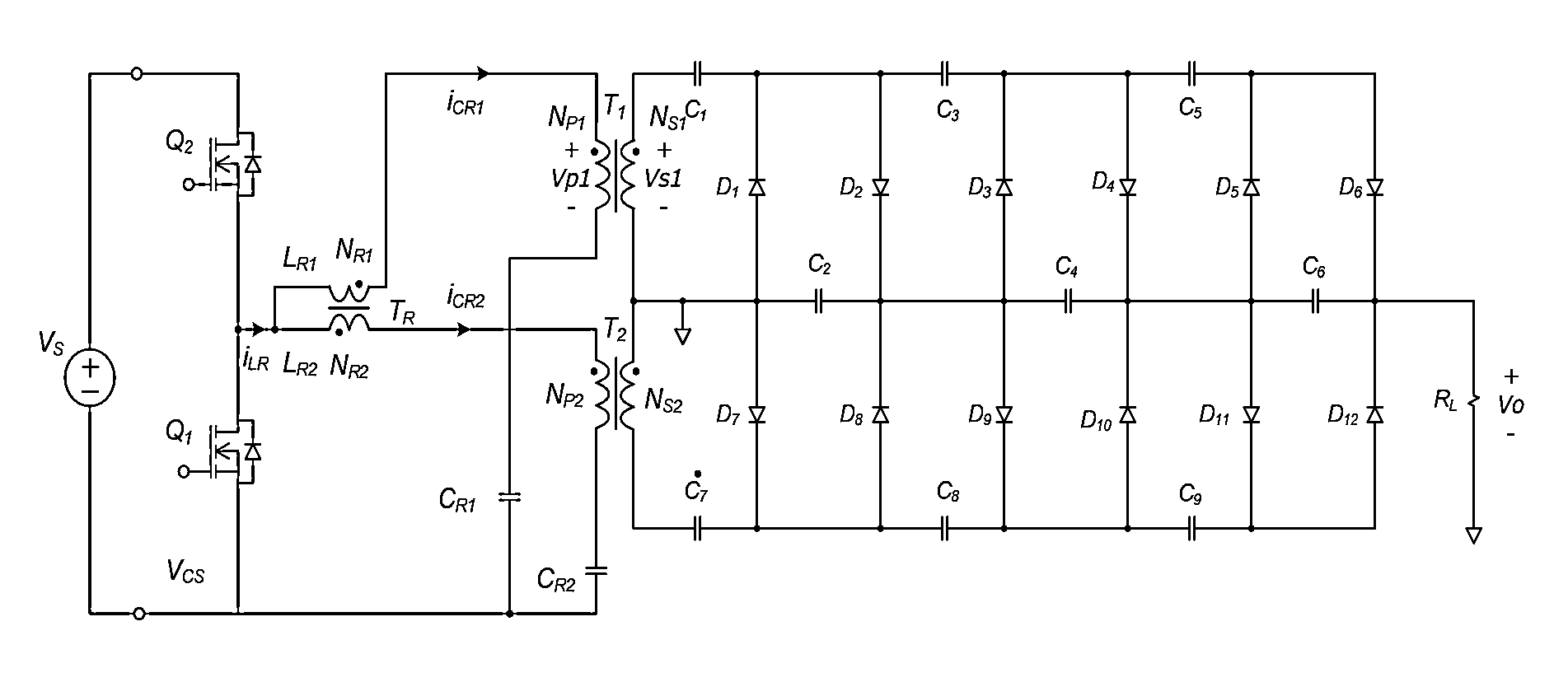
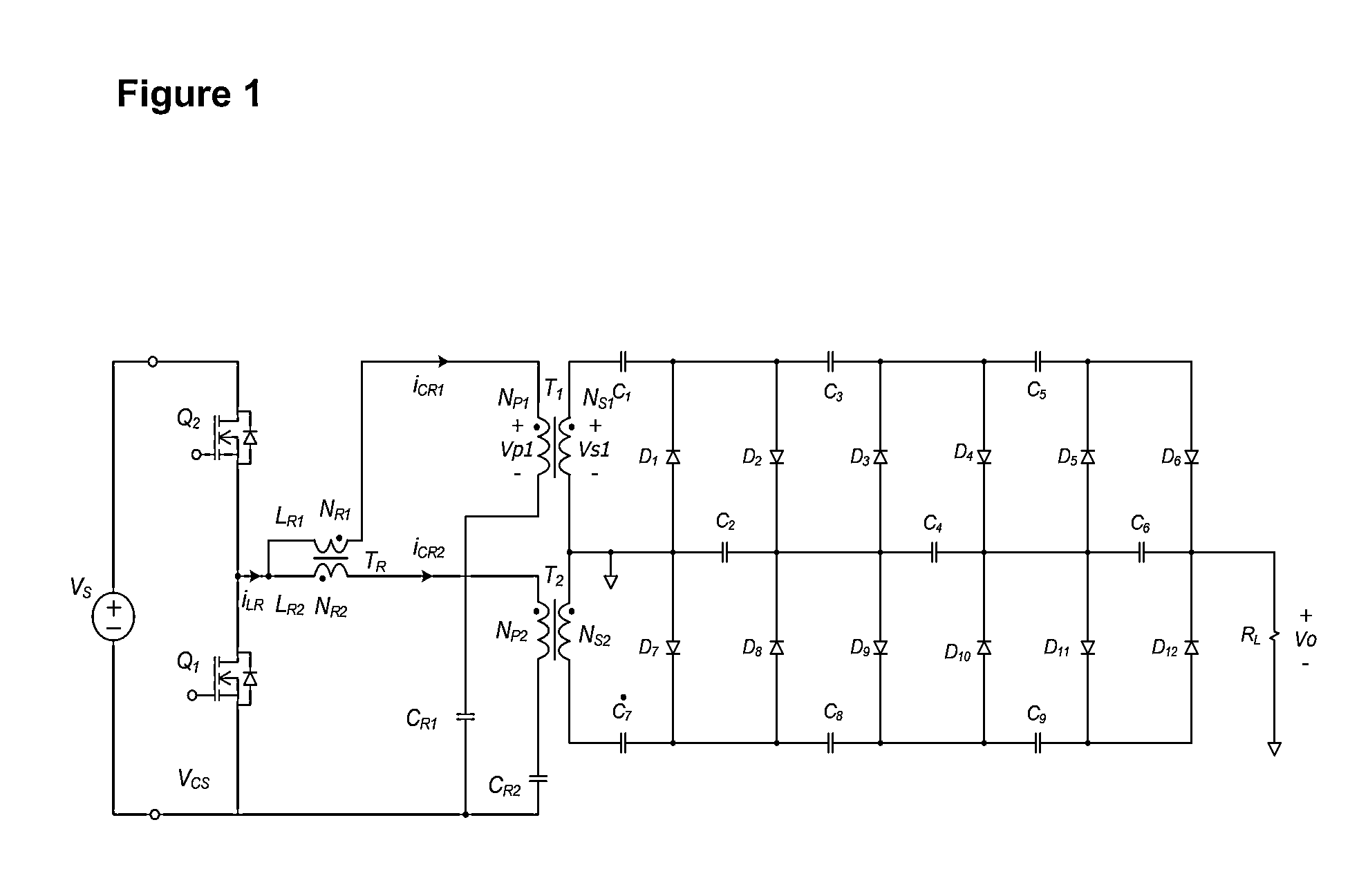
[0027]FIG. 1 is a circuit diagram illustrating a high voltage switching power supply which employs a dual resonance circu...


PUM


Abstract

A dual resonance circuit is formed of two transformers, two resonance inductors and two resonance capacitors for a resonance type switching power supply employing parallel connected transformers. The secondary winding of the transformer is configured in a center tap structure, and a top and bottom symmetrical voltage multiplying rectifier is connected to the secondary winding coupled with the parallel connected transformers, thereby obtaining the same effect as when one transformer is used. The present invention achieves a low loss in the typical resonance type half bridge power supply even though two transformers are employed, and the switching power supply with a lowered height and thinned structure can be provided with the aid of the optimized arrangements of the resonance devices. The internal power loss can be lowered by using two parallel connected transformers as compared to a resonance type switching power supply which employs one transformer.

Description

TECHNICAL FIELD[0001]The present invention relates to a switching power supply, and in particular to a high voltage switching power supply which makes it possible to easily manufacture a compact-sized, thinner switching power supply in such a way to use two parallel connected transformers, which consequently divides the whole size of a transformer adapted to a switching power supply, the switching power supply comprising a top and bottom symmetrical voltage multiplying rectifier at a secondary winding coupled to each of parallel connected transformers.BACKGROUND ART[0002]Some power loss is inevitable in a switching power supply because it is configured to constantly supply power and to convert lots of power. The power which loses inside is generally converted into heat, and the converted heat radiates to the outside, so a power conversion efficiency lowers in proportion to the converted heat. In worse case, the service life of product may be shortened accordingly. As for a large cap...

Claims


Application Information

Patent Timeline
Patent Type & Authority Applications(United States)
IPC IPC(8): H02M3/337
CPCH02M3/337H02M3/3376H02M7/103H02M3/33571H02M3/01H02M3/28H02M3/24H02M3/22H02M1/42
Inventor AN, TAE-YOUNG
Owner CHEONGJU UNIV IND & ACADEMY COOPERATION FOUND
Why Eureka
Try Eureka