

Six-stroke cycle engine having scavenging stroke
a cycle engine and six-stroke technology, applied in the direction of machines/engines, output power, combustion air/fuel air treatment, etc., can solve the problem of inability to reduce pumping loss, and achieve the effect of reducing pumping loss and reducing pumping loss
- Summary
- Abstract
- Description
- Claims
- Application Information
AI Technical Summary
Benefits of technology
Problems solved by technology
Method used
Image

Examples
first preferred embodiment
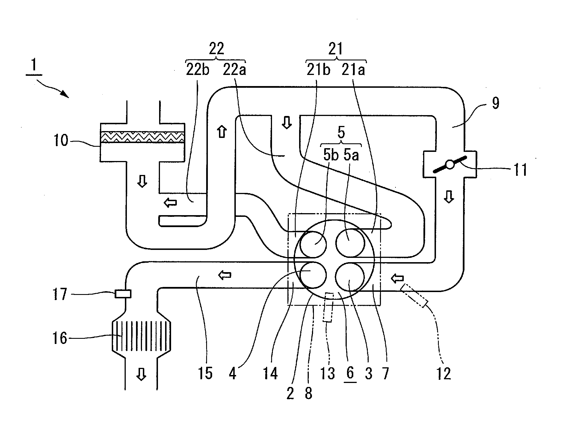
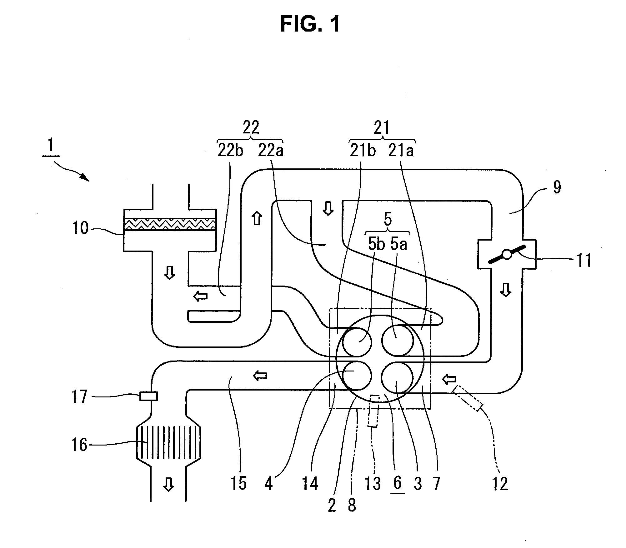
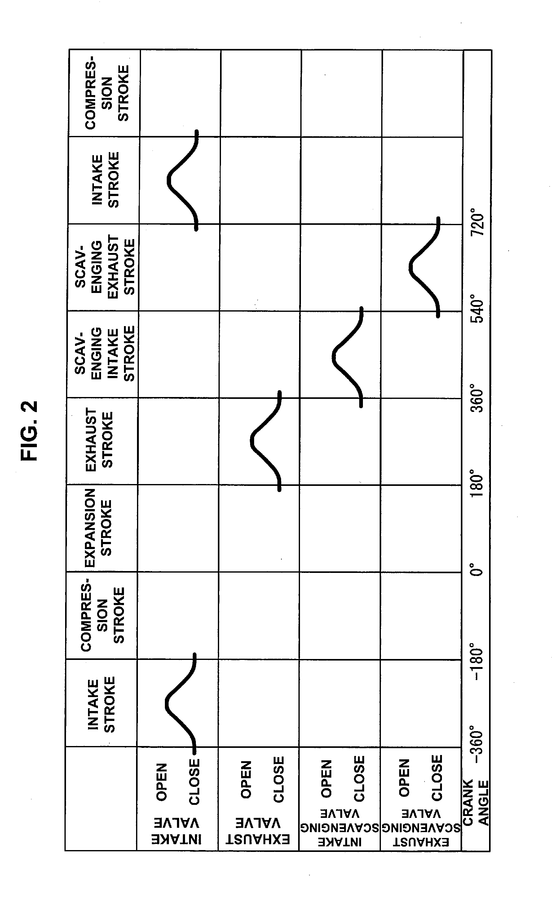
[0029]A six-stroke cycle engine including a scavenging stroke according to a preferred embodiment of the present invention will now be described in detail with reference to FIGS. 1 and 2.
[0030]A six-stroke cycle engine 1 shown in FIG. 1 includes an intake valve 3, an exhaust valve 4, and a scavenging valve 5 in one cylinder 2. FIG. 1 illustrates only one cylinder 2. However, preferred embodiments of the present invention are applicable not only to a single cylinder engine but also to a multiple cylinder engine.
[0031]The intake valve 3 opens and closes an intake port 7 open to a combustion chamber 6. One intake valve 3 is provided for the cylinder 2, for example. The intake valve 3 operates by driving of a valve gear 8 (to be described below). The intake port 7 defines the downstream end of an intake passage 9. The upstream end of the intake passage 9 is open to the atmosphere via an air cleaner 10. A throttle valve 11 is provided in the intake passage 9. The fuel for the six-stroke ...
second preferred embodiment
[0045]When a scavenging valve includes an intake scavenging valve and an exhaust scavenging valve, the arrangement shown in FIG. 3 may be used. The same reference numerals as described with reference to FIGS. 1 and 2 denote the same or similar elements in FIG. 3, and a detailed description thereof will appropriately be omitted.
[0046]A six-stroke cycle engine 1 shown in FIG. 3 includes two intake valves 3. The intake valves 3 are provided on both sides of an intake scavenging valve 5a. When the arrangement using two intake valves 3 is used, as shown in FIG. 3, the intake air volume increases. It is therefore possible to further improve the output.
third preferred embodiment
[0047]A six-stroke cycle engine whose scavenging valve includes an intake scavenging valve and an exhaust scavenging valve may include a supercharger, as shown in FIGS. 4 and 5. The same reference numerals as described with reference to FIGS. 1 to 3 denote the same or similar members in FIGS. 4 an 5, and a detailed description thereof will appropriately be omitted.
[0048]The six-stroke cycle engine 1 shown in FIG. 4 includes a supercharger 31 in the six-stroke cycle engine 1 shown in FIG. 1. The six-stroke cycle engine 1 shown in FIG. 5 includes the supercharger 31 in the six-stroke cycle engine 1 shown in FIG. 3. The supercharger 31 according to the present preferred embodiment is preferably a turbocharger including a turbine 31a on the side of an exhaust passage 15, and a compressor 31b on the side of an intake passage 9. The intake passage 9 according to the present preferred embodiment includes an intercooler 32 on the upstream side of a throttle valve 11. The intercooler 32 cool...
PUM
 Abstract
Description
Claims
Application Information