Crown for an aircraft tire

Active Publication Date: 2014-12-18
MICHELIN & CO CIE GEN DES ESTAB MICHELIN
View PDF13 Cites 8 Cited by
  • Summary
  • Abstract
  • Description
  • Claims
  • Application Information

AI Technical Summary

Benefits of technology

[0012]The inventors have therefore set themselves the objective of reducing the dimensions and therefore the mass of the pieces of tread in the event of a

Problems solved by technology

Of the failure modes considered, the partial or complete loss of the tread of a tire with which an aircraft landing gear is equipped, is a critical failure mode that occurs during aeroplane takeoff or landing phases.
This failure mode occurs, in particular, when the tire runs over a blunt object that might by chance be present on the runway.
Bearing in mind the harsh conditions of use of an aeroplane tire, which are characterized by a high inflation pressure, a high static loading and a high speed, the tread of the tire running over the blunt object causes damage to the tread which generally results in the cutting of the tread and then in pieces of tread of varying geometric dimensions and mass being thrown up.
The pieces of tread may then either strike the structures of the aeroplane and lead to significant structural damage, because of the mechanical energy stored up by the said pieces, the higher the mass and speed at which the pieces are thrown up, the higher this mechanical energy is, or may enter the aeroplane engines and lead to problems with the operation of the said engines, if these engines are unable to absorb the pieces of tread because they are too great in size.
However, for the same materials, this solution entails incr

Method used


Image

  • Crown for an aircraft tire
  • Crown for an aircraft tire
  • Crown for an aircraft tire

Examples


Example

[0060]In order to make the invention easier to understand, FIGS. 1 to 7 have not been drawn to scale and are simplified depictions.

DETAILED DESCRIPTION OF SPECIFIC EMBODIMENTS

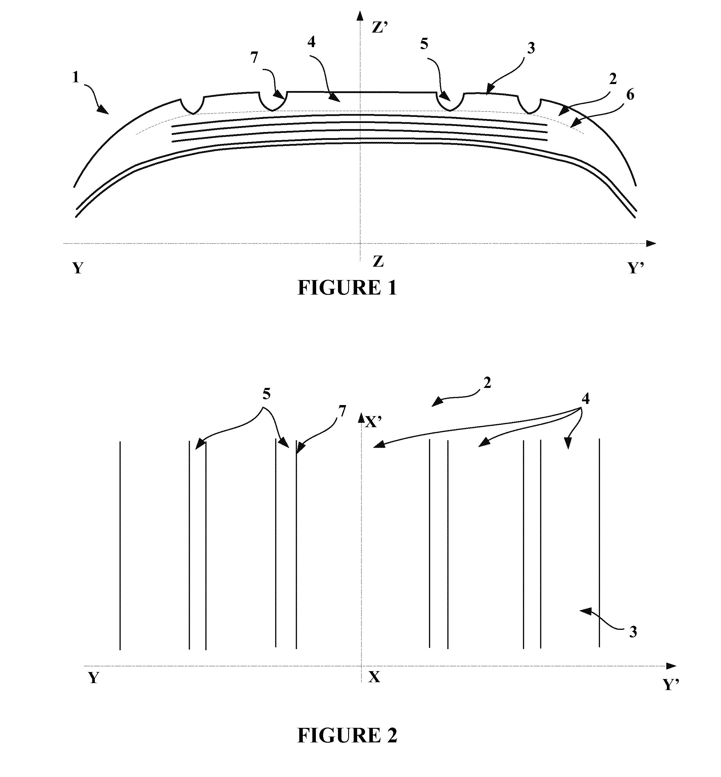
[0061]FIG. 1 shows a meridian section through the crown of the tire 1, namely a section in a meridian plane (YY′, ZZ′), in which the directions YY′ and ZZ′ are the axial and radial directions respectively.

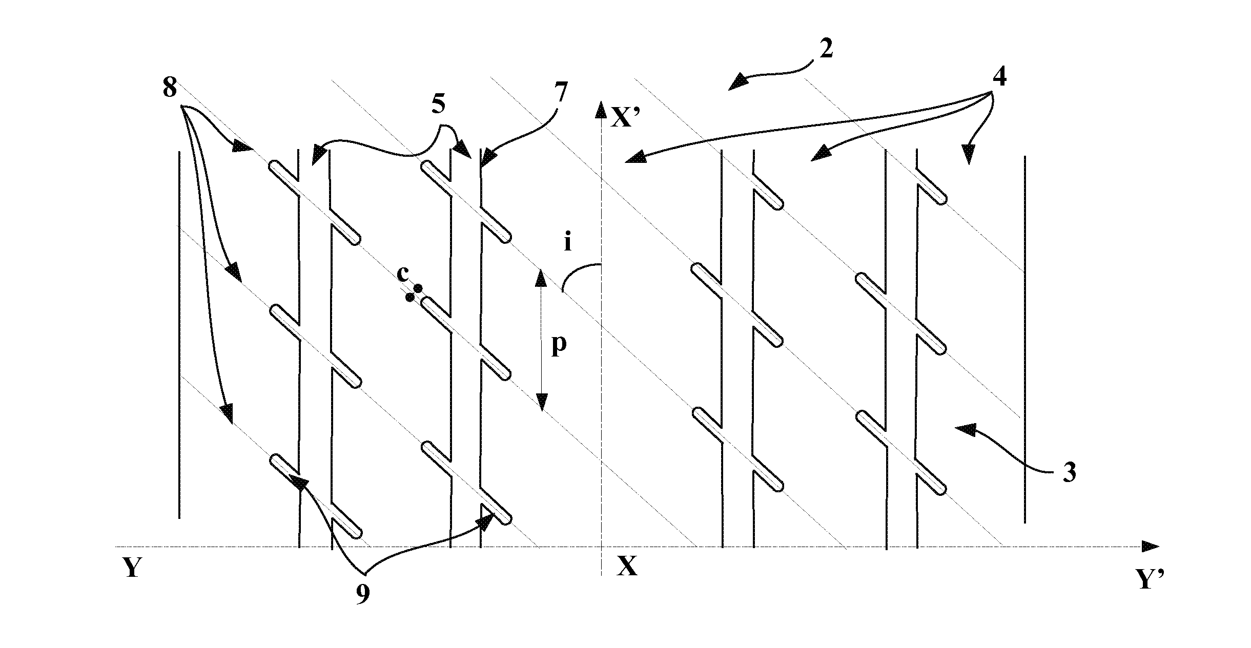
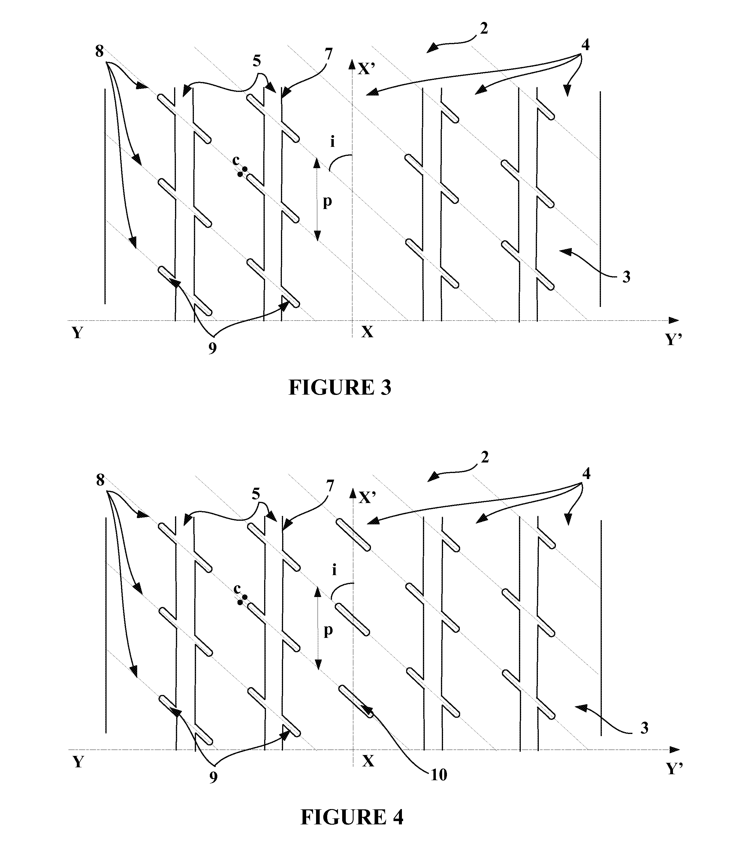
[0062]FIG. 1 shows a tire 1 for an aeroplane comprising a tread 2 intended to come into contact with the ground via a tread surface 3, and comprised radially between a bottom surface 6 and the tread surface 3. The tread 2 comprises five circumferential ribs 4, in this instance adjacent to at least one circumferential groove 5. Each circumferential rib 4 extends radially between the bottom surface 6 and the tread surface 3 and axially between two lateral faces 7 that form the walls of the circumferential groove 5. The tire 1 also comprises a crown reinforcement 8, made up of crown layers, radially on the inside...


PUM


Abstract

A tire for an aeroplane and, in particular, to the crown of a tire for an aeroplane, having reduced dimensions and mass of the pieces of tread in the event of accidental tire tread separation, without the use of additional devices external to the tire and therefore without penalizing the payload of the aeroplane, having a tread intended to come into contact with the ground via a tread surface, and extending radially between a bottom surface and the tread surface, the tread comprising at least two circumferential ribs adjacent to at least one circumferential groove, each circumferential rib extending radially between the bottom surface and the tread surface, axially between two lateral faces and circumferentially around the entire periphery of the tire, wherein the tread comprises rows of cavities formed in at least one circumferential rib and opening onto the tread surface, the rows of cavities, which are parallel to one another, are inclined with respect to the circumferential direction (XX′) of the tire at an angle (i) at least equal to 45°, and the rows of cavities are distributed circumferentially over at least part of the periphery of the tire with a circumferential spacing (p) at least equal to 0.02 times and at most equal to 0.12 times the circumferential length of the periphery of the tire.

Description

[0001]This application is a 371 national phase entry of PCT / EP2012 / 075943, filed 18 Dec. 2012, which claims benefit of FR 1162030, filed 20 Dec. 2011, the entire contents of which are incorporated herein by reference for all purposes.BACKGROUND[0002]1. Field[0003]The present invention relates to a tire for an aeroplane and, in particular, to the crown of an aeroplane tire.[0004]2. Description of Related Art[0005]Aeroplane manufacturers are constantly concerned with passenger safety and, therefore, with reducing the risks of failure of their craft. Of the failure modes considered, the partial or complete loss of the tread of a tire with which an aircraft landing gear is equipped, is a critical failure mode that occurs during aeroplane takeoff or landing phases.[0006]This failure mode occurs, in particular, when the tire runs over a blunt object that might by chance be present on the runway. Bearing in mind the harsh conditions of use of an aeroplane tire, which are characterized by a...

Claims


Application Information

Patent Timeline
IPC IPC(8): B60C11/04
CPCB60C11/04B60C2011/0372B60C2011/0358B60C11/032B60C11/1259B60C11/1272B60C2011/0381B60C2011/133B60C2200/02
Inventor CHAMBRIARD, FRANCOISROCHE, GILLES
Owner MICHELIN & CO CIE GEN DES ESTAB MICHELIN
Why Eureka
Try Eureka