Mobile imaging platform calibration

a mobile imaging and calibration technology, applied in the field of computing, can solve the problems of high cost of recalibration, distortion, other forms of corruption, high calibration process cost, etc., and achieve the effect of reducing inefficiencies, fast and more accurate techniques

Active Publication Date: 2014-12-18
MICROSOFT TECH LICENSING LLC
View PDF2 Cites 63 Cited by
  • Summary
  • Abstract
  • Description
  • Claims
  • Application Information

AI Technical Summary

Benefits of technology

[0005]Upon identifying the laser scanner path, the camera path, and the location sensor path, the platform may compare these paths to verify the maintenance of the calibration of the sensors. In an embodiment, the coordinate system of each sensor is registered with a static coordinate system, and the translation and orientation changes between each pair of points in a first sensor path of a first sensor of the platform may be compared with the corresponding translations and orientation changes between each pair of points in a second sensor path of another sensor of the platform. Matching comparisons may verify the continued calibration of the sensors, while mismatches (e.g., discrepancies in the detected translation and orientation change of the platform over time) may indicate that at least one sensor has become miscalibrated. Additionally, a three-way comparison of the laser scanner path with the camera path, the laser scanner path with the location sensor path, and the camera path with the location sensor path (as well as comparisons among paths of equivalent sensors, e.g., comparing a first camera path detected by a first camera and a second camera path detected by a second camera) may identify the miscalibrated device. By performing such calibration checking using the computation and comparison of paths for each device, the techniques presented herein may enable periodic and / or continuous verification of maintained calibration even while the platform continues to travel, and / or a faster and more accurate technique for detecting a miscalibration, which may reduce inefficiencies caused by the miscalibration. These and other uses of such calibration techniques may be included in many embodiments of the techniques presented herein.

Problems solved by technology

Reconstructing the area 102 with a variance between the presumed orientation and the actual orientation of the sensor may result in visual artifacts, distortions, and other forms of corruption.
However, the calibration process may be expensive and protracted, and a sensor that is subjected to a physical jolt while the platform 104 is traveling may result in a recall of the platform 104 to the controlled setting for recalibration, possibly entailing a high cost of recalibration, and / or leaving the platform 104 out of service for a potentially extended duration.
However, if one or more of the comparisons 312 fails to produce a match, a miscalibration may be detected.

Method used


Image

  • Mobile imaging platform calibration
  • Mobile imaging platform calibration
  • Mobile imaging platform calibration

Examples


Embodiment Construction

[0016]The claimed subject matter is now described with reference to the drawings, wherein like reference numerals are used to refer to like elements throughout. In the following description, for purposes of explanation, numerous specific details are set forth in order to provide a thorough understanding of the claimed subject matter. It may be evident, however, that the claimed subject matter may be practiced without these specific details. In other instances, structures and devices are shown in block diagram form in order to facilitate describing the claimed subject matter.

A. INTRODUCTION

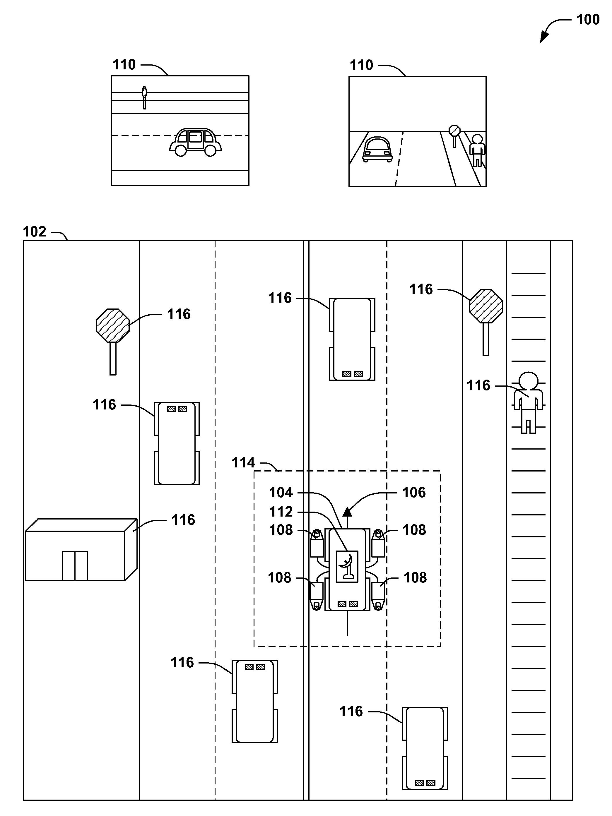
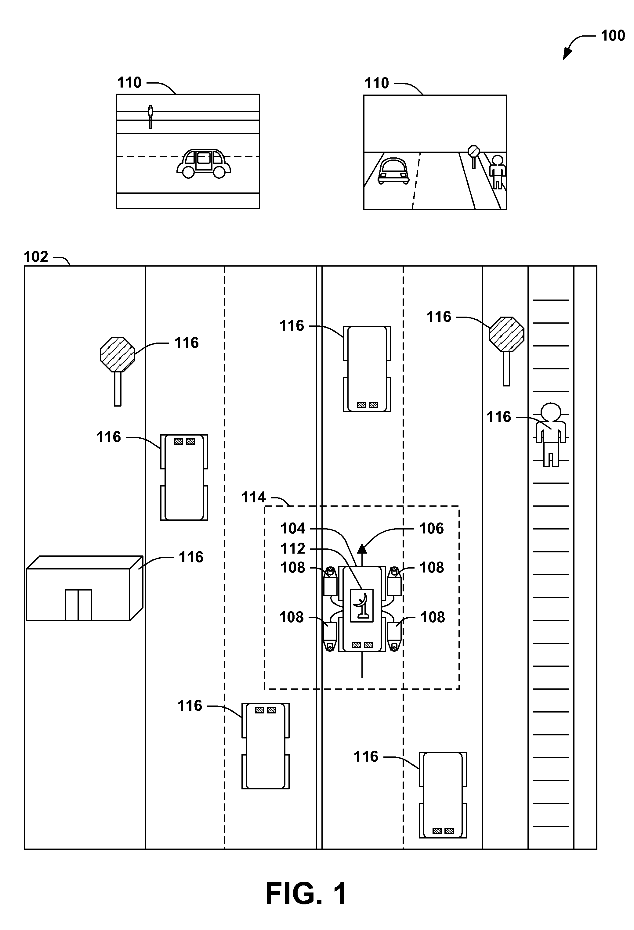
[0017]FIG. 1 presents an illustration of a first exemplary scenario 100 featuring a platform 104 traveling through an area 102 while capturing a representation of the area 102 using a variety of sensors. While the platform 104 is mobile (e.g., exhibiting a particular motion vector 106 with respect to the stationary objects of the area 102), the mobile platform may use one or more cameras 108, posit...


PUM


Abstract

Mobile platforms are used to capture an area using a variety of sensors (e.g., cameras and laser scanners) while traveling through the area, in order to create a representation (e.g., a navigable set of panoramic images, or a three-dimensional reconstruction). However, such sensors are often precisely calibrated in a controlled setting, and miscalibration during travel (e.g., due to a physical jolt) may result in a corruption of data and / or a recalibration that leaves the platform out of service for an extended duration. Presented herein are techniques for verifying sensor calibration during travel. Such techniques involve the identification of a sensor path for each sensor over time (e.g., a laser scanner path, a camera path, and a location sensor path) and a comparison of the paths, optionally after registration with a static coordinate system, to verify that the continued calibration of the sensors during the mobile operation of the platform.

Description

BACKGROUND[0001]Within the field of computing, many scenarios involve a scanning of a mobile platform provided to travel through an area and capture a representation of the area. For example, an automobile equipped with one or more cameras may be driven through a road network of a city while capturing images of the city, which are later stitched together to form a navigable pictorial tour of the city. As another example, a scan of the area using laser scanners of various types, such as light detection and ranging (“lidar”) scanners, may result in the capturing of spatial information about the area that enables a three-dimensional reconstruction of the geometry of the area. These and other techniques may be utilized to capture and reconstruct various types of representations of an area.SUMMARY[0002]This Summary is provided to introduce a selection of concepts in a simplified form that are further described below in the Detailed Description. This Summary is not intended to identify ke...

Claims


Application Information

Patent Timeline
Patent Type & Authority Applications(United States)
IPC IPC(8): G06T7/00G01S17/02G06T3/00G01S17/86
CPCG06T7/00G06T7/0018G01S17/023G06T3/00G06T7/002G01S17/42G01S7/4972H04N13/156G01S17/86H04N23/698G06T7/80
Inventor IRSCHARA, ARNOLDSCHWEIGHOFER, GERALDKARNER, KONRADLADSTADTER, RICHARDPONTICELLI, MARTIN
Owner MICROSOFT TECH LICENSING LLC
Why Eureka
Try Eureka