
Turbulence-free camera system and related method of image enhancement

a technology of turbulence-free camera and related method, which is applied in image enhancement, television system, instruments, etc., can solve the problems of not obtaining detailed information about subject matter of classic cameras, such as aerial photos, and limited spatial resolution, so as to avoid the effect of affecting reducing the image quality of the image,

Inactive Publication Date: 2014-12-18
UNIV OF MARYLAND BALTIMORE COUNTY
View PDF2 Cites 13 Cited by
  • Summary
  • Abstract
  • Description
  • Claims
  • Application Information

AI Technical Summary

Benefits of technology

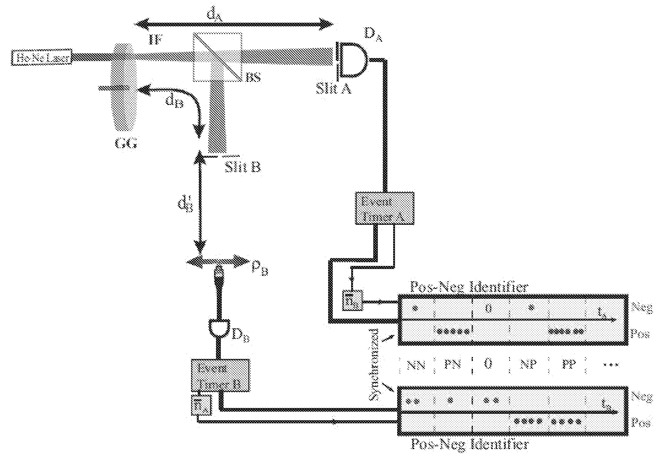
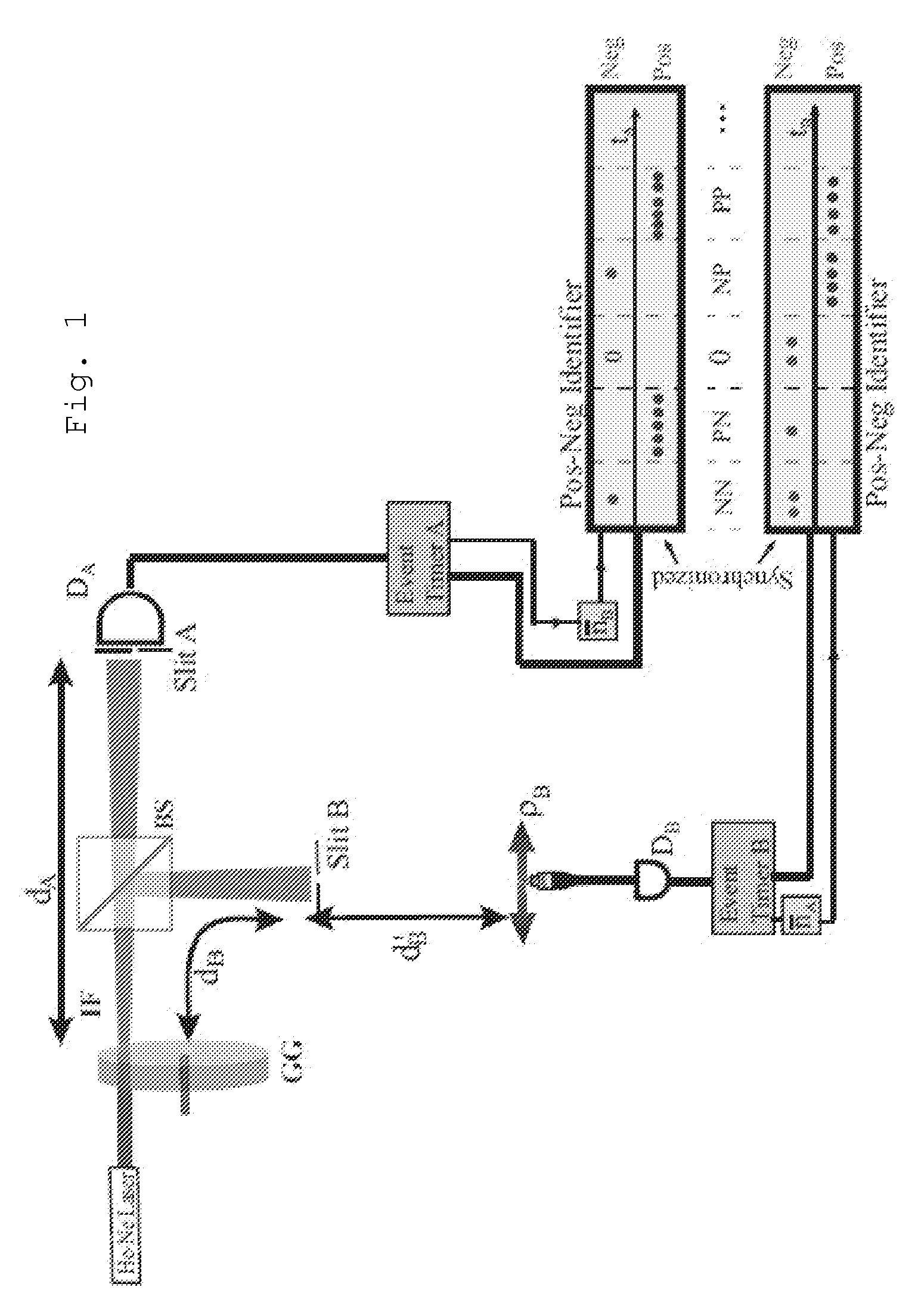
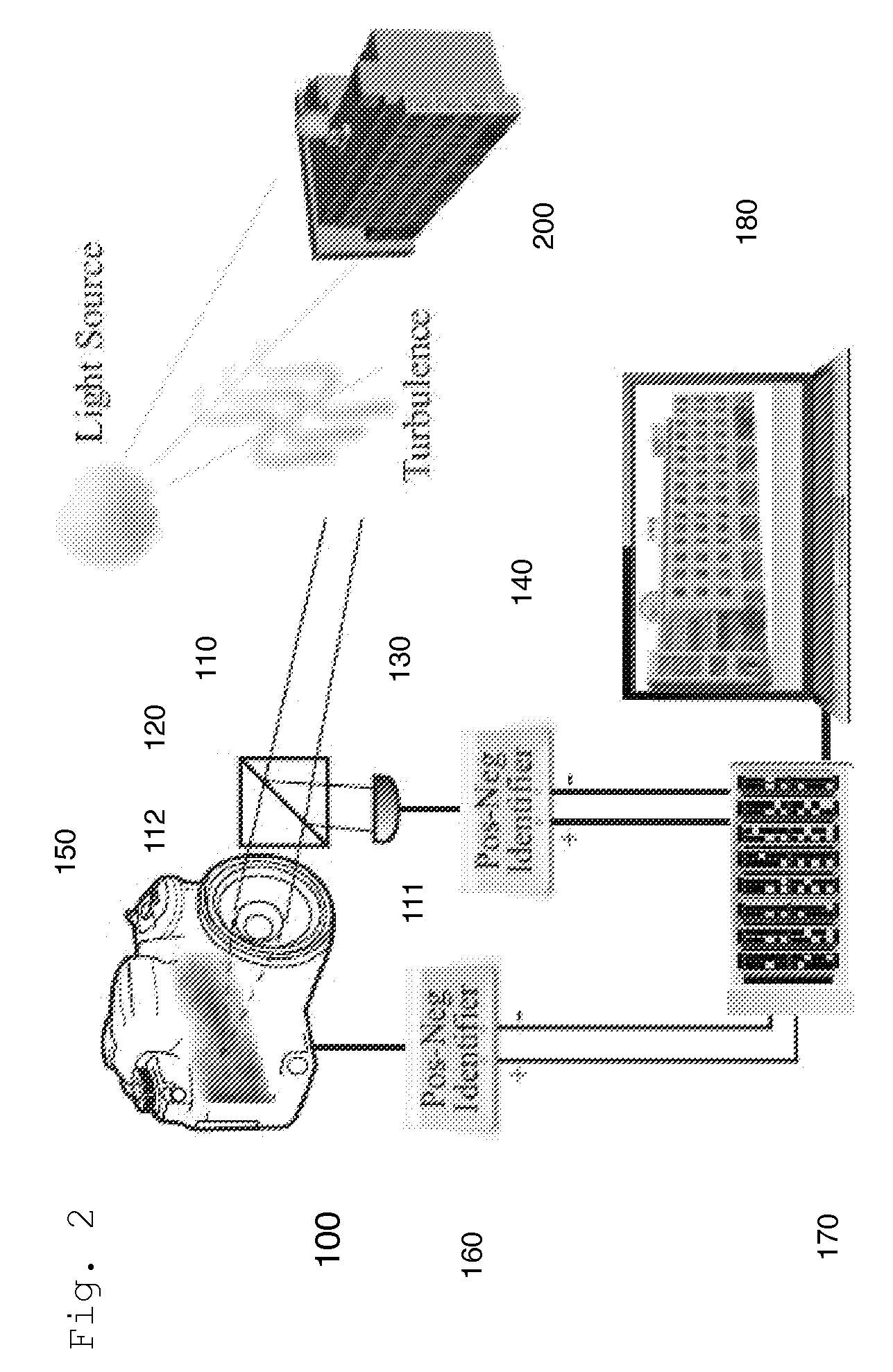
The patent describes a camera system that can detect and analyze thermal light photons from an object or area to be imaged. The system uses a beam splitter to receive the photons and passes them to two positives-negative (Pos-Neg) identifiers. These identifiers then pass information to a positive-negative fluctuation circuit (PNFC) which detects photon coincidence from the intensity fluctuation correlation of sunlight and calculates the resulting correlation information for an image viewer. The PNFC can also determine the intensity of the measured light field and count the number of photons in each frame. The camera system can create an improved image by averaging and modifying the pixel values. It can also be located on a satellite, airplane, helicopter, drone or other aerial vehicle. The system can also be used to detect and analyze the effects of turbulence or adverse weather effects on the thermal light photons.

Problems solved by technology

Classic cameras taking pictures from great distances, such as aerial photos, may not obtain detailed information about the subject matter.
Although a classic camera with a “small” lens may be able to “zoom” into a small area, its limited spatial resolution would not allow the classic camera to distinguish the objects within that small area.

Method used


Image

  • Turbulence-free camera system and related method of image enhancement
  • Turbulence-free camera system and related method of image enhancement
  • Turbulence-free camera system and related method of image enhancement

Examples


example 1

Construction of Prototype Turbulence-free CCD camera

[0072]In this example a prototype turbulence-free CCD camera is developed that is able to take second-order turbulence-free images.

[0073]Materials

[0074]The prototype unit consists of a commercial research grade CCD camera, and hardware and software to interface with the PNFC system. Intensity fluctuation-fluctuation correlation calculations, involving large-dimensional matrix algebra, are conducted using commercial PCs and multi-crosstalk graphic cards.

[0075]CCD Camera

[0076]Based on the optical and electronic parameters of the CCD camera, the hardware parts are designed for a ghost imaging system including the PNFC system and the hardware-interface between the CCD camera and the PNFC protocol as well as coincidence-measurement circuits. This results in a working PNFC system and hardware interface between the CCD camera and the PNFC.

[0077]Multi-Crosstalk Graphic Cards

[0078]The software is developed for multi-crosstalk graphic cards ...


PUM


Abstract

A turbulence-free CCD camera system with nonclassical imaging resolution, for applications in long- distance imaging, such as satellite and aircraft-to-ground based distant imaging, utilizing an intensity- fluctuation correlation measurement of thermal light. The proposed camera system has the following advantages over classic imaging technology: (1) it is turbulence-free; (2) its spatial resolution is mainly determined by the angular diameter of the light source. For example, using sun as the light source, this camera may achieve a spatial resolution of 200 micrometer for any object on Earth. 200-micrometer resolution is insignificant for short distance imaging, however, taking a picture of a target at 10-kilometer, a classic camera must have a lens of 90-meter diameter in order to achieve 200-micrometer resolution. Unlike a classic camera, the proposed turbulence-free CCD camera system has adequate spatial resolution zoom a long distance and still distinguish the objects within a small area, even with a small lens.

Description

CROSS REFERENCE TO RELATED APPLICATIONS[0001]This patent application claims priority to U.S. provisional patent application 61 / 835,778, filed Jun. 17, 2013, the contents of which are incorporated herein in their entirety.STATEMENT REGARDING FEDERALLY SPONSORED RESEARCH OR DEVELOPMENT[0002]This invention was made with government support under FA9550-09-1-0489-2 awarded by AFOSR, and W911NF-11-2-0074 awarded by ARL. The government has certain rights in the invention.NAMES OF PARTIES TO A JOINT RESEARCH AGREEMENT[0003]Not applicable.SEQUENCE LISTING INCLUDED AND INCORPORATED BY REFERENCE HEREIN[0004]Not applicable.BACKGROUND[0005]1. Field of the Invention[0006]The invention relates to a turbulence-free camera with enhanced spatial resolution and full color reproduction.[0007]In 1956, astrophysicists Hanbury Brown and Twiss (HBT) invented the intensity interferometer and achieved a much more accurate measurement on the angular size of distant stars. Unlike the Michelson stellar interfer...

Claims


Application Information

Patent Timeline
IPC IPC(8): H04N5/372
CPCH04N5/372H04N23/56H04N23/63H04N23/74H04N25/71H04N25/626G06T2207/10032G06T2207/30181G01J2001/428G01N2021/4106H04N23/45H04N25/60G01N21/41G02B27/1066
Inventor SHIH, YANHUACHEN, HUIPENG, TAO
Owner UNIV OF MARYLAND BALTIMORE COUNTY
Learn More