Multi-functional exercise machine

a multi-functional, exercise machine technology, applied in the direction of walking aids, resilient force resistors, physical therapy, etc., can solve the problems of increasing the chance of injury and decreasing the efficiency of exercise, and achieve the effect of saving and improving efficiency

Inactive Publication Date: 2014-12-18
ELLIS JOSEPH K
View PDF19 Cites 22 Cited by
  • Summary
  • Abstract
  • Description
  • Claims
  • Application Information

AI Technical Summary

Benefits of technology

[0011]The present invention provides a safer and more efficient method of exercising that imitates natural human motion by moving the user through multiple planes of motion during the exercise regimen. The invention can be configured into several different embodiments for exercising different muscles or groups of muscles. All of the embodiments contain the common feature of the user support being directly and pivotally connected to a linear sliding or rolling member that allows the user support to move in a linear path while concurrently pivoting throughout the range of motion of the exercise. In some embo...

Problems solved by technology

This forces the user's body to conform to a less than natural motion i...

Method used


Image

  • Multi-functional exercise machine
  • Multi-functional exercise machine
  • Multi-functional exercise machine

Examples


fourth embodiment

[0159]Referring now to FIGS. 27-29, exploded views of another embodiment of the invention is shown. In this embodiment, tubes also are generally are similar in shape, size, and structure to each other and can comprise three (3) or four (4) sections 334, 336, 338, 340. The first section 334 acts as a front riser and extends backwardly and horizontally or upwardly, and preferably horizontally or only slightly upwardly, from the front stand 330. The second section 336 extends generally upwardly and backwardly from the first section 334 comprises an extension 202 extending generally upwardly and generally downwardly from the second section. The lever arm 316 is pivotally attached to the generally downwardly extending portion 204 of the extension 202 and the resistance or assistance mechanism 318 is pivotally attached to the generally upwardly extending portion 206 of the extension 202. The third section comprises a downward facing arch and fulcrum 342 for pivotably supporting second lin...

first embodiment

[0178]the invention shown in FIGS. 27-34 is termed a core trainer, and is based on the base machine disclosed above, wherein the user support is pivotably connected to the traveling member proximal to one end of the user support and connected to the linkage mechanism proximal to the opposite end of the user support such that both ends of the user support connection points support a substantial amount of the users weight during at least a portion of the exercise motion.

[0179]In this embodiment, the user engagement member can be a lever arm 316 pivotably mounted to the main frame 312 proximal to the opposite end of the frame from the user support 314, whereby urging of the lever arm 316 by the user's hands, arms, and torso towards the user support and urging of the user support by the user's feet, legs, and hips towards the lever arm 316 creates a concurrent exercise motion of upper and lower body muscle groups.

[0180]Also in this embodiment, when the machine 10 is activated by the use...

second embodiment

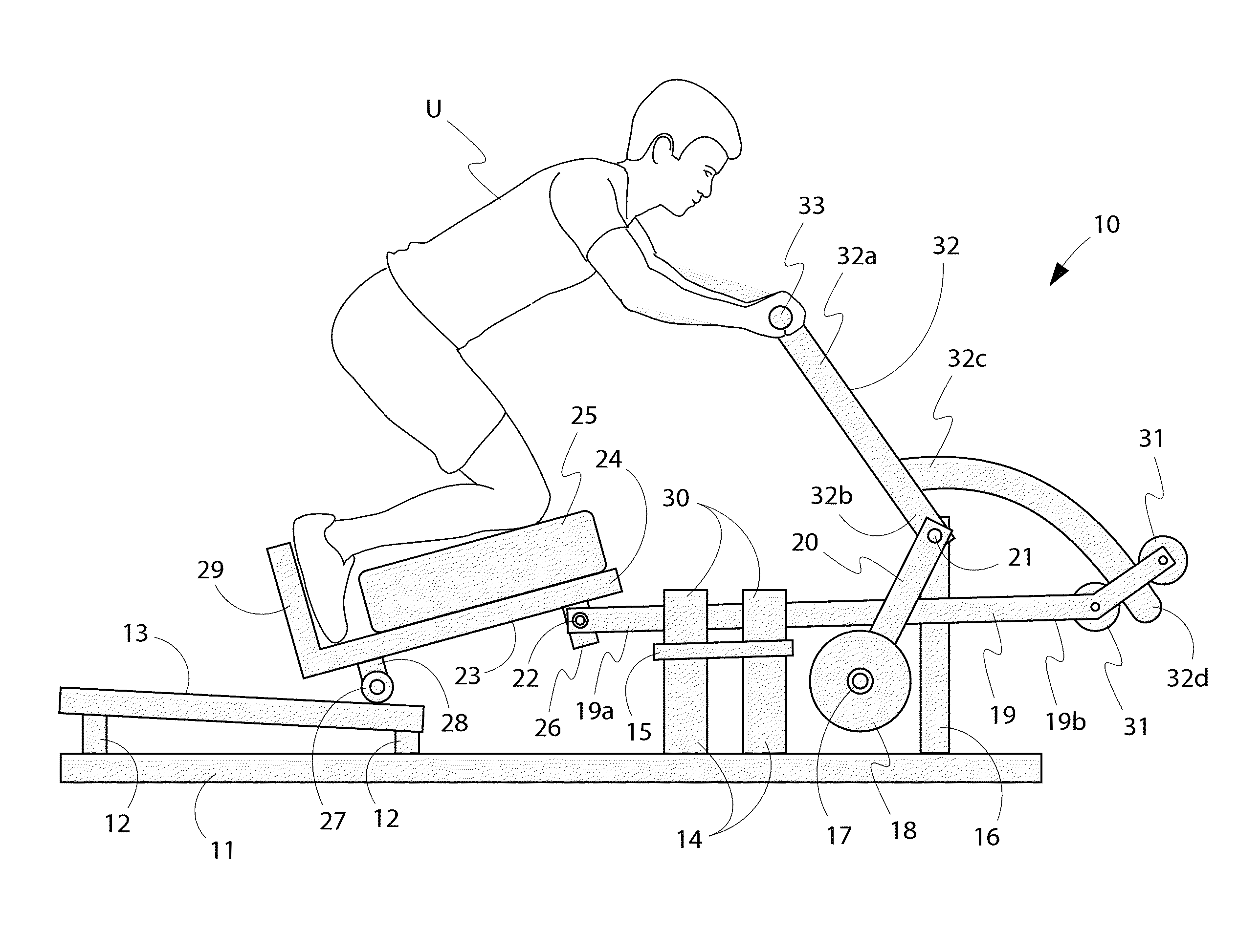
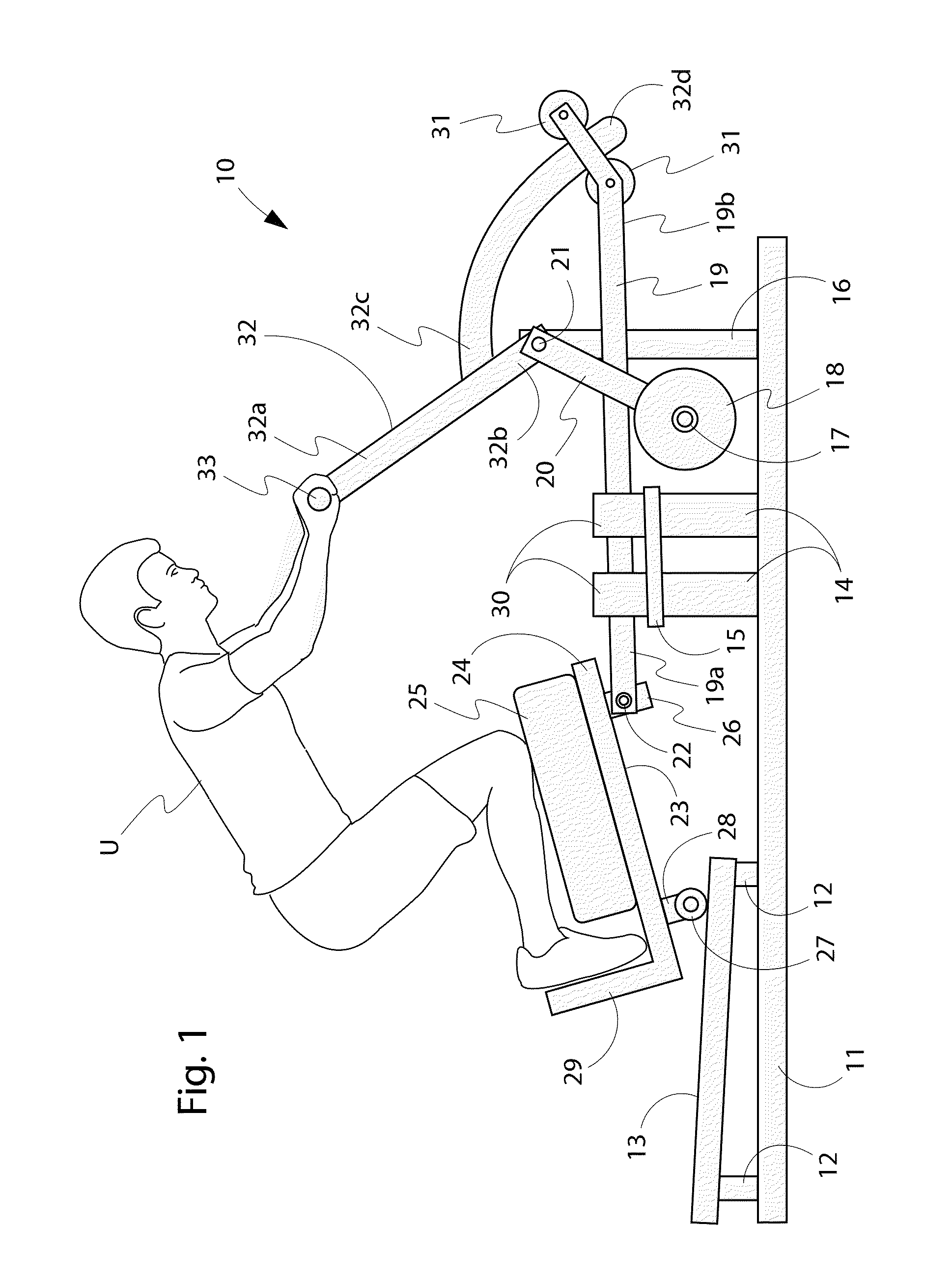
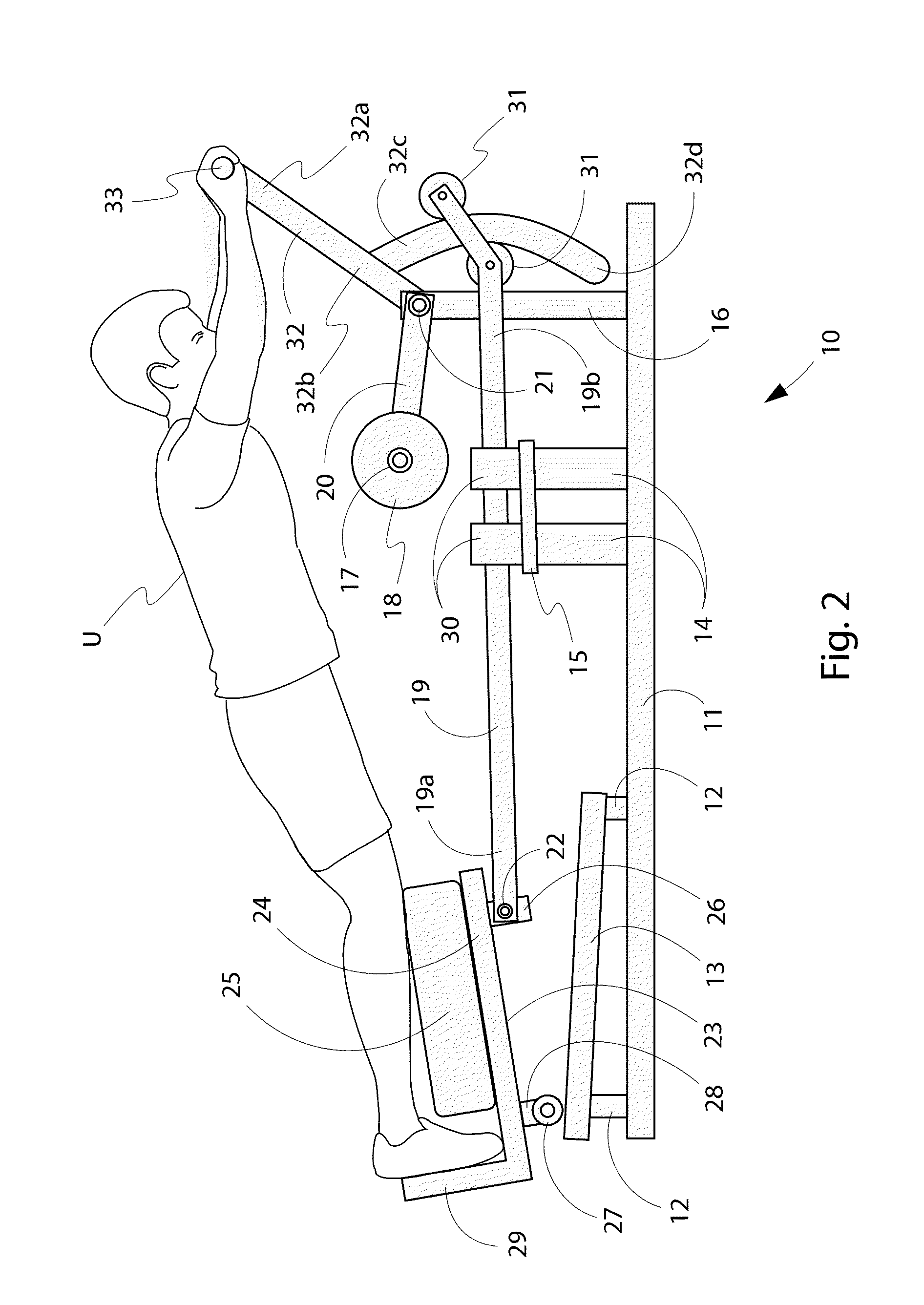
[0187]the invention FIGS. 1-4 is termed a total body press, and is based on the base machine disclosed above, wherein the user engagement member is an lever arm 32 pivotably mounted to the main frame 11 proximal to the opposite end of the frame from the user support 23, whereby urging of the lever arm 32 by the user's hands, arms, and torso away from the user support 23 and urging of the user support 23 by the user's feet, legs, and hips away from the lever arm 32 creates a concurrent exercise motion of upper and lower body muscle groups. The user support 32 can comprise a pad 27 to support the user's lower legs.

[0188]Also in this embodiment, the user support 23 can comprise a rigid member 29 to support the user's feet during the exercise motion. This rigid member 29 can be located proximal to the back end of the user support 23 and opposite the end to which the linkage mechanism 19 connects. This rigid member 29 can be of sufficient size and strength to withstand the pushing force ...


PUM


Abstract

A machine for concurrently exercising one or more of a user's muscle groups, the machine having a base having front and back ends, one or more linear slide rails, a user support and an engagement member for the user's hands or feet. The user support slides while pivoting during the exercise motion such that the location and angle of the user support is dictated by the linkage mechanism that positions and connects the user support relative to the other parts of the machine. The user support can be caused to move by the engagement member being acted upon by the user's feet only, by the user's hands only or a combination of the user's feet and hands concurrently during the exercise.

Description

STATEMENT OF RELATED APPLICATIONS[0001]This patent application claims the benefit of U.S. patent application Ser. No. 14 / 148,303 having a filing date of 6 Jan. 2014, which claims the benefit of U.S. patent application Ser. No. 13 / 967,188 having a filing date of 14 Aug. 2013, which claims the benefit of U.S. patent application Ser. No. 13 / 992,744 having a filing date of 9 Jun. 2013, which claims the benefit of International Application No. PCT / US2011 / 065738 having an international filing date of 19 Dec. 2011.BACKGROUND OF THE INVENTION[0002]1. Technical Field[0003]This invention relates to the general technical field of exercise, physical fitness and physical therapy equipment and machines. This invention relates more specifically to the field of exercise equipment for concurrently exercising in multiple planes of motion.[0004]2. Prior Art[0005]Exercise, physical fitness and physical therapy equipment and machines are available in various configurations and for various purposes, and ...

Claims


Application Information

Patent Timeline
IPC IPC(8): A63B21/00
CPCA63B21/00032A63B21/00069A63B21/00181A63B21/008A63B21/0085A63B21/012A63B21/02A63B21/0615A63B21/068A63B21/159A63B22/14A63B22/205A63B23/0205A63B23/0222A63B23/0227A63B23/03525A63B2208/0219A63B2225/09A63B21/0628A63B21/4033A63B21/4035A63B21/4047A63B21/4049A63B22/001A63B21/4034
Inventor ELLIS, JOSEPH K.
Owner ELLIS JOSEPH K
Why Eureka
Try Eureka