Manually operated in-cup milk frothing appliance

a technology for frothing appliances and milk, which is applied in beverage vessels, household applications, kitchen equipment, etc., can solve the problems of inability to operate in humid kitchen environments, high labor intensity, and inability to meet the needs of users,

Inactive Publication Date: 2014-12-25
KONINKLIJKE PHILIPS ELECTRONICS NV
View PDF2 Cites 4 Cited by
  • Summary
  • Abstract
  • Description
  • Claims
  • Application Information

AI Technical Summary

Benefits of technology

[0007]It is an object of the present invention to provide for a milk frothing device that overcomes or mitigates one or more of the aforementioned drawbacks associated with known milk frothers. More in particular, it is an object of the present invention to provide for a milk frothing device that is economically manufacturable, reliable, does not demand extensive cleaning after use and enables a design free of a plurality of external controls.

Problems solved by technology

A disadvantage of the steam wand is that its operation requires skill on the part of the user, in particular since the optimal position of the steam outlet relative to the milk surface is rather sensitive.
The electronic components in known milk frothing devices make their manufacture rather costly, and their operation in generally humid kitchen environments susceptible to failure.
The risk of moist-induced defects is particularly imminent for stirrer-type frothers, of which at least the internal liquid tank must be thoroughly cleaned after each use to maintain the hygiene of the device.

Method used


Image

  • Manually operated in-cup milk frothing appliance
  • Manually operated in-cup milk frothing appliance
  • Manually operated in-cup milk frothing appliance

Examples


Embodiment Construction

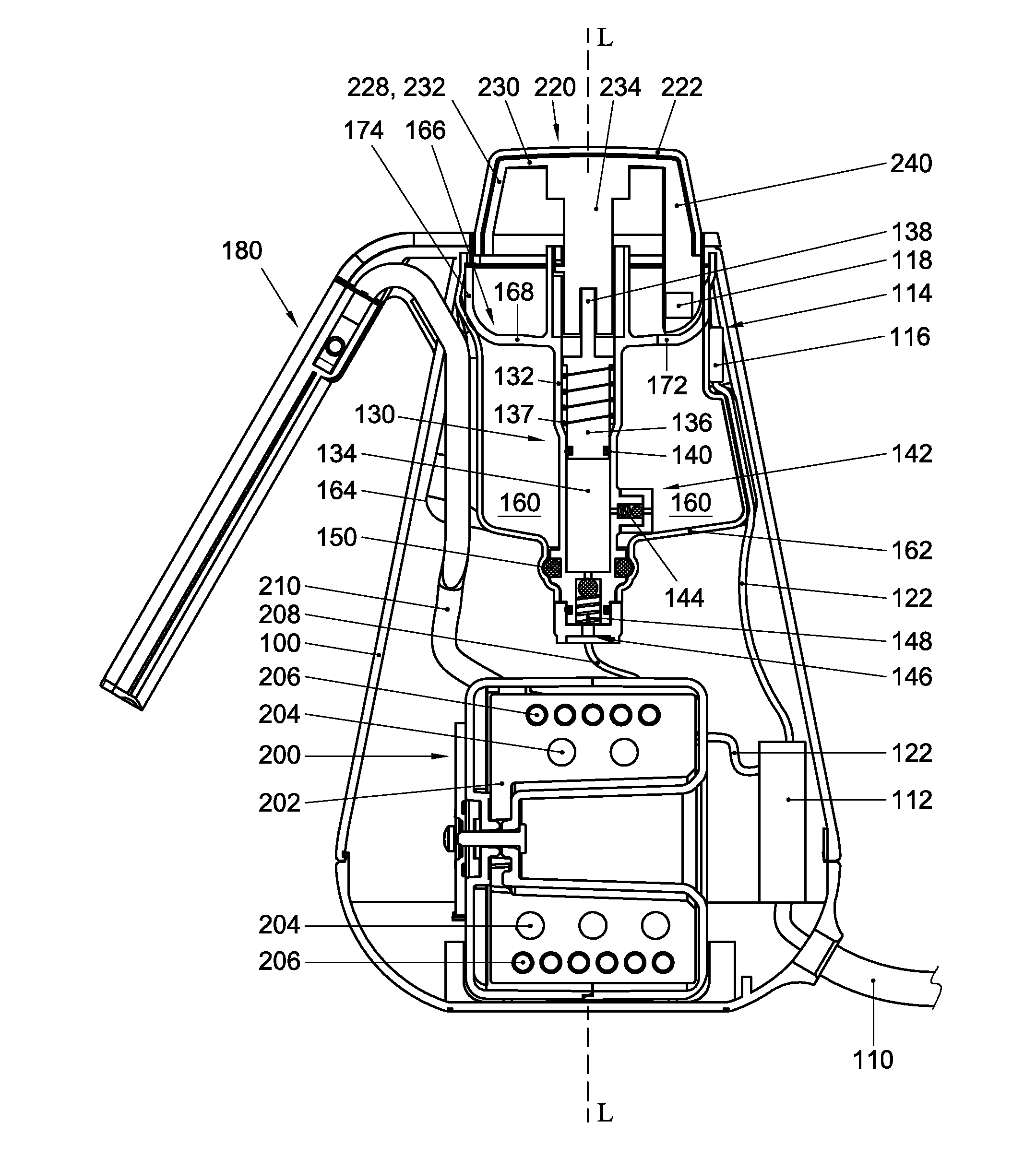
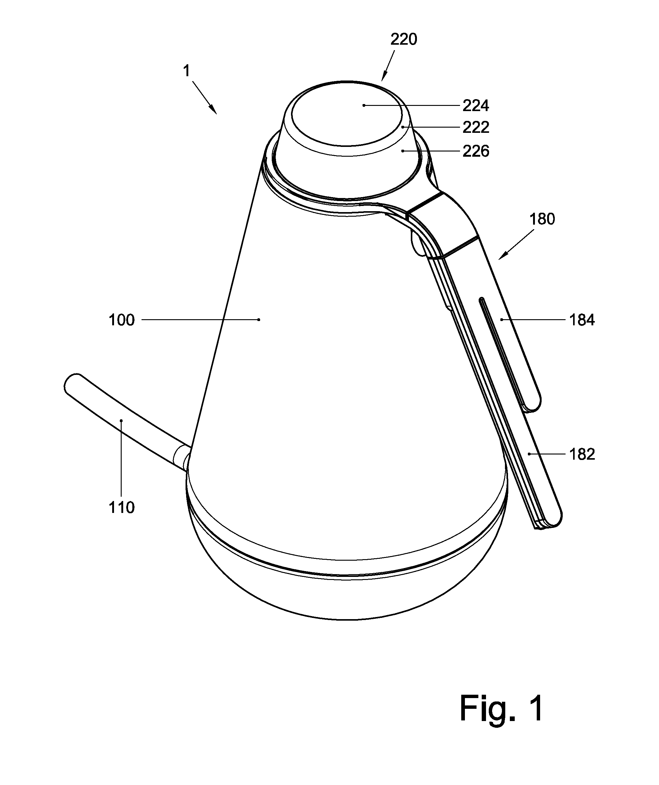
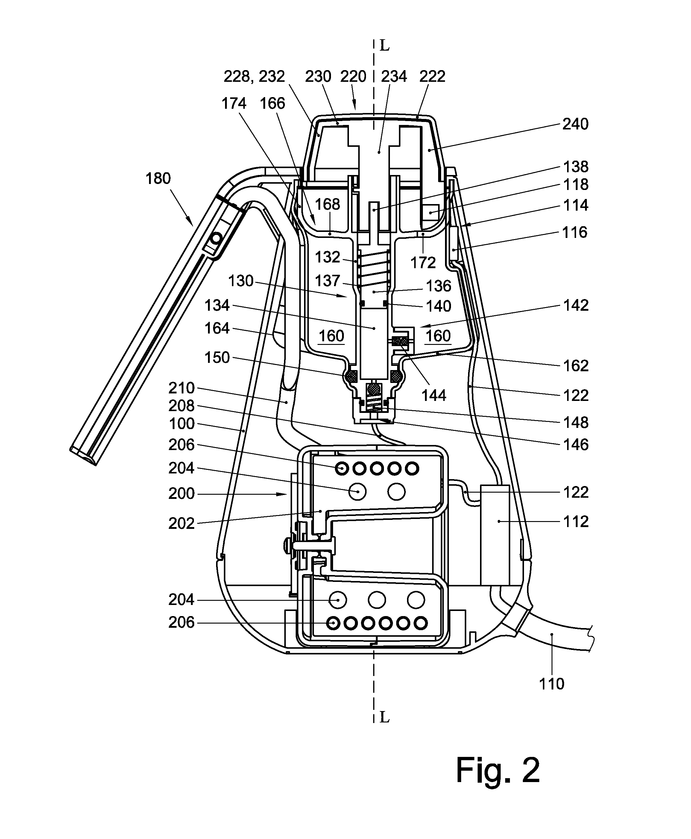
[0022]FIGS. 1-6 schematically illustrate an exemplary embodiment of a milk frothing appliance 1 according to the present invention, whose construction and operation are discussed below.

[0023]As can be seen best in FIGS. 1 and 2, the milk frothing appliance 1 may include a generally conical body 100 that accommodates a water reservoir 160, a steam generator 200, most of a hand pump 130 for transferring water from the water reservoir 160 to the steam generator 200, and an electrical controller 112. The appliance 1 may further include an actuator 220, which may be disposed on top of the body 100 and be considered to form a part of the hand pump 130, and a milk frothing device 180 that is connected to the body 100 and extends sideways therefrom in a slopingly downward direction. The water reservoir 160, the hand pump 130, the steam generator 200 and milk frothing device 180 may be fluidly connected in series, in that order.

[0024]The water reservoir 160 may be defined by a bottom wall 16...


PUM


Abstract

A milk frothing appliance (1), comprising:—a water reservoir (160);—a steam generator (200);—a milk frothing device (180) that is fluidly connected to the steam generator (200); and—a hand pump (130) that is fluidly connected to both the water reservoir and the steam generator, comprising a manually operable actuator (220) that is moveable between a first actuator position and a second actuator 138 position, and that upon movement from the first actuator position into the second actuator position causes displacement of fluid from the water reservoir to the steam generator (200).

Description

FIELD OF THE INVENTION[0001]The present invention relates to an apparatus for frothing a liquid food product. Since apparatus of this type are commonly used to froth milk, the apparatus is referred to as a milk frothing appliance in the text that follows.BACKGROUND[0002]Milk frothing appliances are available in different types. Some milk frothing appliances, for instance, are integrated into coffee machines, while others are configured for stand-alone use.[0003]An example of an integrated milk frothing appliance is the ‘steam wand’ that is customarily built-in in espresso machines. To froth milk, a steam outlet of the steam wand is positioned in a cup of milk, at or just below the surface of the milk. Then the steam wand is turned on so as to effect the ejection of a jet of steam that, as it impacts the air-milk interface, causes the production of an milk-air-steam mixture which results in the desired froth. A disadvantage of the steam wand is that its operation requires skill on th...

Claims


Application Information

Patent Timeline
Patent Type & Authority Applications(United States)
IPC IPC(8): A47J31/44
CPCA47J31/44A47J31/4489
Inventor BRUINSMA, RODIN ENNEVAN DER WONING, MARK RONALD
Owner KONINKLIJKE PHILIPS ELECTRONICS NV
Why Eureka
Try Eureka