

Stall floor heat exchanger reducing heat stress and lameness
a heat exchanger and stall technology, applied in the field of stall floor heat exchangers, can solve the problems of poor heat exchange effect, less milk produced by cows, and higher rates of debilitating diseases, and achieve the effects of reducing elasticity, reducing elasticity, and facilitating cleaning and maintenan
- Summary
- Abstract
- Description
- Claims
- Application Information
AI Technical Summary
Benefits of technology
Problems solved by technology
Method used
Image

Examples
Embodiment Construction
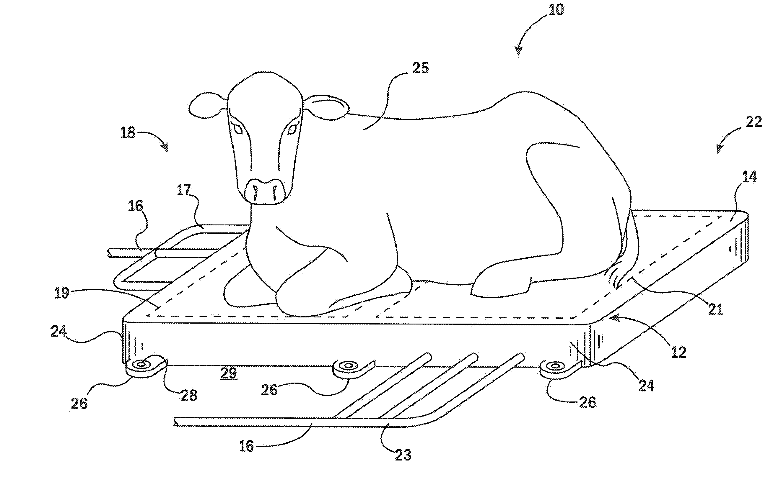
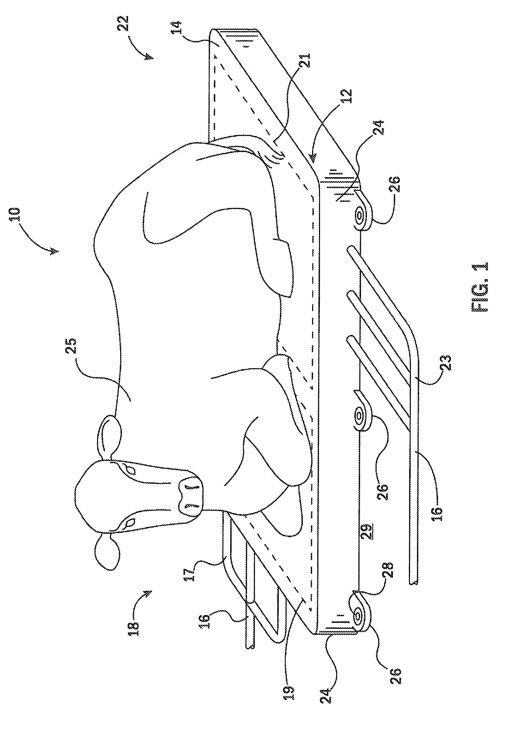
[0048]Referring now to FIG. 1, a heat exchanger system 10 according to the present invention may provide for a generally planar rectangular elastic mat 12 having a substantially continuous upper surface 14, and in one example having an area of approximately 4 feet in width and 6 feet in length and a vertical thickness of 2 to 4 inches. In some embodiments, the mat 12 provides an area that can substantially fully support a reclining cow.
[0049]Water inlet lines16 are attached to a superior end 18 of the mat 12 to introduce water into a superior region 19 of the mat 12, the superior region 19 intended to be positioned under the front quarters of a cow 25 lying on the mat 12. Corresponding water outlet lines 20 are attached to a left side of the inferior end 22 of the mat 12 near an inferior region 21, the latter intended to be positioned under the hindquarters of the cow 25. Each of the water inlet lines 16 and water outlet lines 20 connect, through a mat sidewall 24, with the interior...
PUM
 Abstract
Description
Claims
Application Information