Attenuation reduction grounding structure for differential-mode signal transmission lines of flexible circuit board

a flexible circuit board and differential-mode signal technology, applied in printed circuits, high-frequency circuit adaptations, printed circuit details, etc., can solve the problems of poor signal transmission reliability, attenuation of signals, affecting the performance and reliability of transmission of high-frequency signals, etc., to achieve excellent grounding effect, reduce grounding structure, poor grounding

Active Publication Date: 2014-12-25
ADVANCED FLEXIBLE CIRCUITS
View PDF7 Cites 10 Cited by
  • Summary
  • Abstract
  • Description
  • Claims
  • Application Information

AI Technical Summary

Benefits of technology

[0014]In respect of efficacy, the attenuation reduction grounding structure of differential-mode signal transmission lines of a flexible circuit board provided by the present invention provides the grounding line of the differential-mode signal lines with an excellent grounding effect, so that signal interference caused by poor grounding in the transmission of a high-frequency signal through high-frequency signal lines can be eliminated. Further, with the thin metal foil layer of the present invention comprising a plurality of openings formed at locations corresponding to top angles of the differential-mode signal lines, the differential-mode signal lines is provided with excellent attenuation reduction effect in transmission of a high-frequency signal, whereby excellent effects can be achieved for both performance and reliability of signal transmission.

Problems solved by technology

This leads to interference of signal and affects the performance and reliability of transmission of high-frequency signals.
However, in the transmission of a high-frequency signal, the top angle structures and the bottom angle structures may cause attenuation of the signal.
Such a situation leads to problems of poor signal transmission reliability, poor impedance control, and signal interference in the transmission of a high-frequency signal through the high-frequency signal transmission lines that are commonly used in the contemporarily available electronic devices.

Method used


Image

  • Attenuation reduction grounding structure for differential-mode signal transmission lines of flexible circuit board
  • Attenuation reduction grounding structure for differential-mode signal transmission lines of flexible circuit board
  • Attenuation reduction grounding structure for differential-mode signal transmission lines of flexible circuit board

Examples


Embodiment Construction

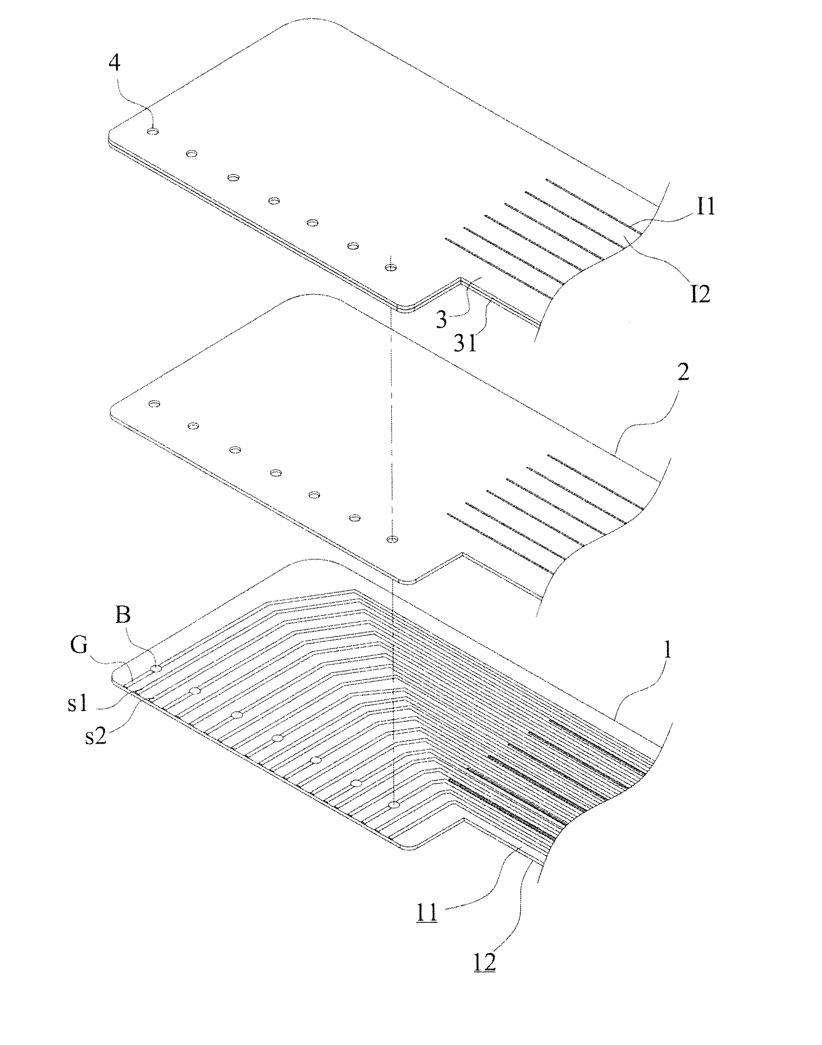
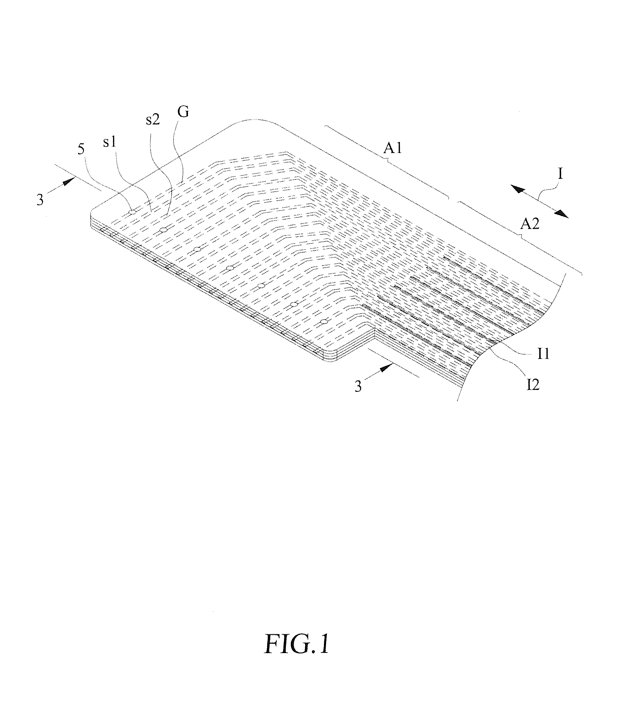
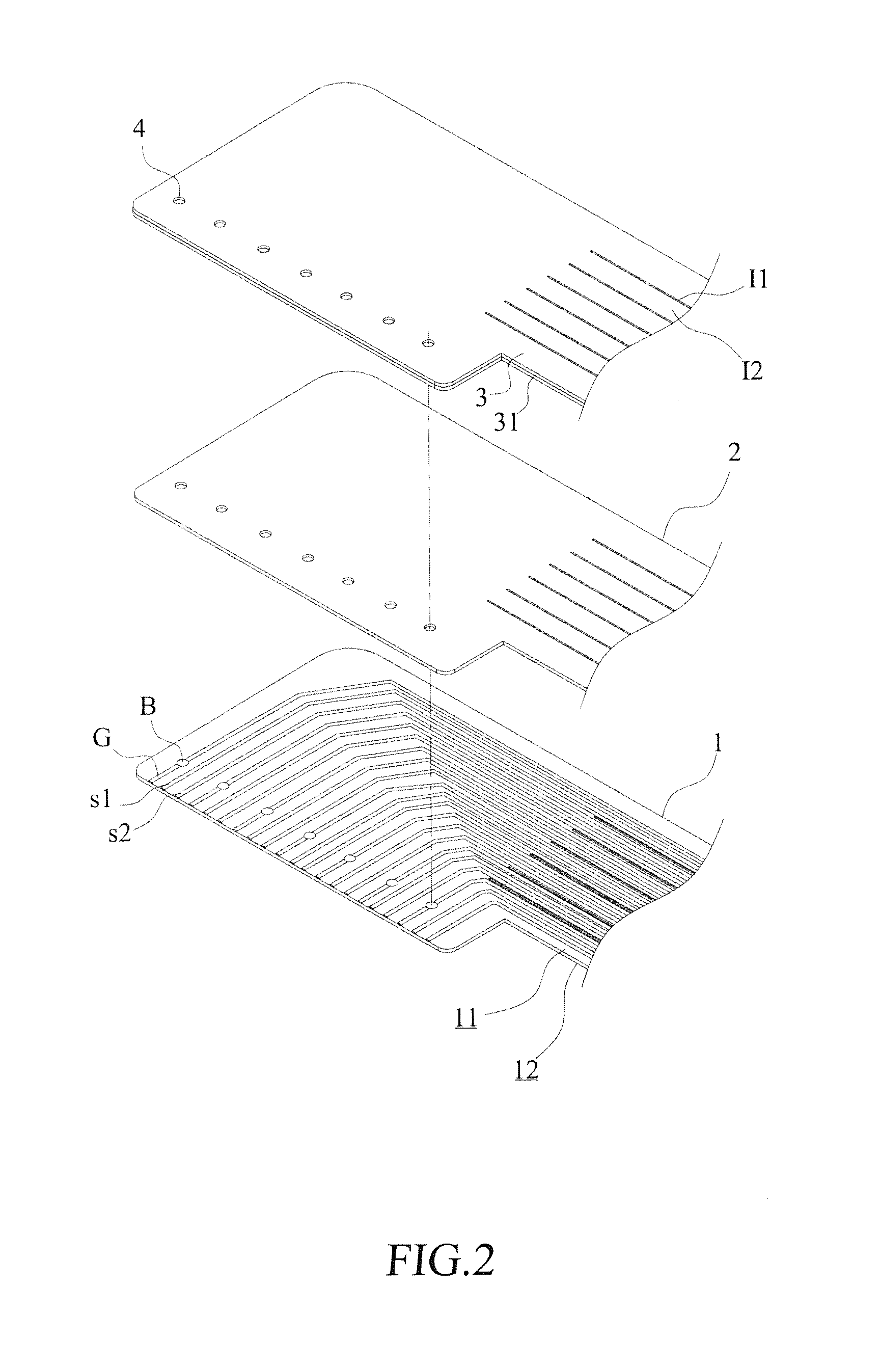
[0024]With reference to the drawings and in particular to FIGS. 1 and 2, which are respectively a perspective view and an exploded view of a first embodiment of the present invention, as shown in the drawings, a flexible substrate 1 extends in an extension direction I and comprises a first surface 11 and a second surface 12. The flexible substrate 1 comprises at least one connection section A1 and an extension section A2 connected to the connection section A1. The flexible substrate 1 is cut, in the extension section A2, to form a plurality of slit lines 11 extending in the extension direction 1 so as to form a plurality of cluster lines 12.

[0025]A plurality of signal lines that is parallel to and spaced from each other by a predetermined distance is formed on the first surface 11 of the flexible substrate 1 to define at least one pair of differential-mode signal lines s1, s2 for transmitting a high-frequency differential-mode signal. The differential-mode signal lines s1, s2 are ge...


PUM


Abstract

An attenuation reduction grounding structure of differential-mode signal transmission lines of a flexible circuit board includes a flexible substrate on which at least one pair of differential-mode signal lines, at least one grounding line, a covering insulation layer, and a thin metal foil layer are formed. At least one via hole extends through the thin metal foil layer and the covering insulation layer and corresponds to a conductive contact zone of the grounding line. The via hole is filled with a conductive paste layer to electrically connect the thin metal foil layer to the conductive contact zone of the grounding line to provide an excellent grounding arrangement. The thin metal foil layer includes a plurality of openings formed at locations corresponding to top angles of the differential-mode signal lines.

Description

BACKGROUND OF THE INVENTION[0001]1. Field of the Invention[0002]The present invention relates to the design of an attenuation reduction grounding structure of high-frequency signal transmission lines of a circuit board, and in particular to an attenuation reduction grounding structure of differential-mode signal transmission lines of a flexible circuit board, which comprises at least one vie hole extending through a thin metal foil layer, a bonding material layer, and a covering insulation layer formed on the flexible circuit board and corresponding to a conductive contact zone of a grounding line, with the via hole being filled with a conductive paste material layer to electrically connect the thin metal foil layer to the conductive contact zone of the grounding line.[0003]2. The Related Arts[0004]Most electronic devices are provided with circuit boards or flexible flat cables to position all necessary circuit components and connectors and realize transmission of electronic signals...

Claims


Application Information

Patent Timeline
Patent Type & Authority Applications(United States)
IPC IPC(8): H05K1/02
CPCH05K1/0237H05K1/0225H05K1/0245H05K1/118H05K3/4069H05K2201/09845
Inventor LIN, GWUN-JINSU, KUO-FUCHUO, CHIH-HENG
Owner ADVANCED FLEXIBLE CIRCUITS
Why Eureka
Try Eureka