System and method for occupancy sensing with enhanced functionality

a technology of occupancy sensing and enhanced functionality, applied in the field of occupancy sensing systems, can solve the problems of low-intensity ambient light failure, high-intensity light and low-intensity light configuration not providing a way, occupancy sensor failure can present a safety hazard,

Active Publication Date: 2014-12-25
LEVITON MFG
View PDF3 Cites 14 Cited by
  • Summary
  • Abstract
  • Description
  • Claims
  • Application Information

AI Technical Summary

Problems solved by technology

Where occupancy sensors are used to control lighting in spaces such as stairwells or other areas where visibility is important, occupancy sensor failure can present a safety hazard because lighting may remain off even when a person has entered the area.
A disadvantage of using a high-intensity light and a low-intensity light configuration is the potential for the low-intensity ambient light failing, and subsequently the occupancy sensor malfunctioning so that the high-intensity light does not turn on when the space is occupied.
Furthermore, a high-intensity light and a low-intensity light configuration does not provide a way to determine if the low-intensity light has failed other than if a person enters the space and visually determines that both the high-intensity light and the low-intensity light have not turned on.
For sensors positioned in elevated locations this is inconvenient and can pose a safety hazard as it requires the user to be on a ladder.
Low voltage occupancy sensors are sensors without a relay, and as such they cannot directly control a connected load.
As will be appreciated, providing separate external interface units can result in increased system cost.
As the ambient temperature of a monitored space rises, the difference between human body temperature and the ambient temperature decreases, and as a result PIR occupancy sensors can be less able to differentiate the heat of a human body from the heat of the surroundings.

Method used


Image

  • System and method for occupancy sensing with enhanced functionality
  • System and method for occupancy sensing with enhanced functionality
  • System and method for occupancy sensing with enhanced functionality

Examples


Embodiment Construction

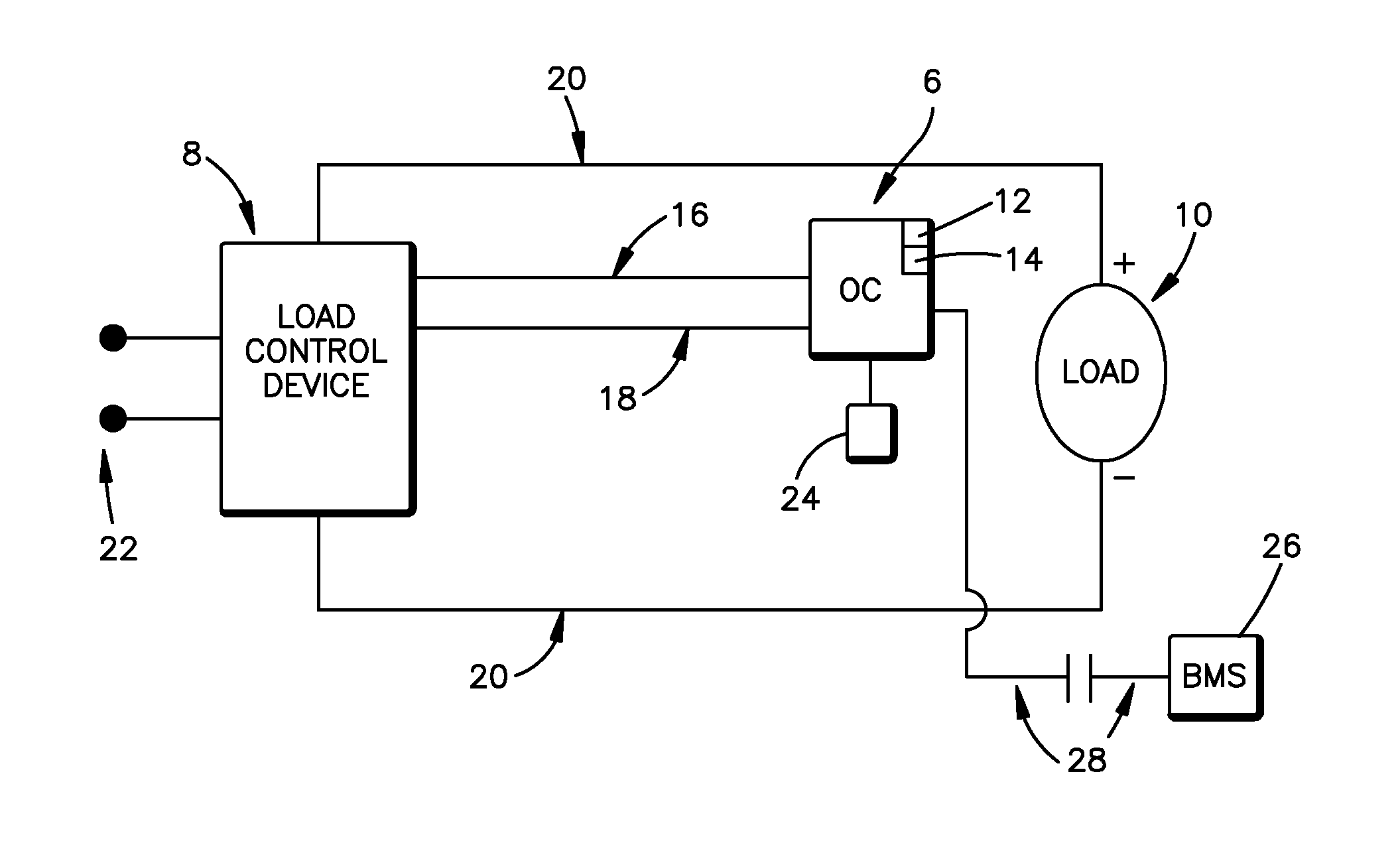
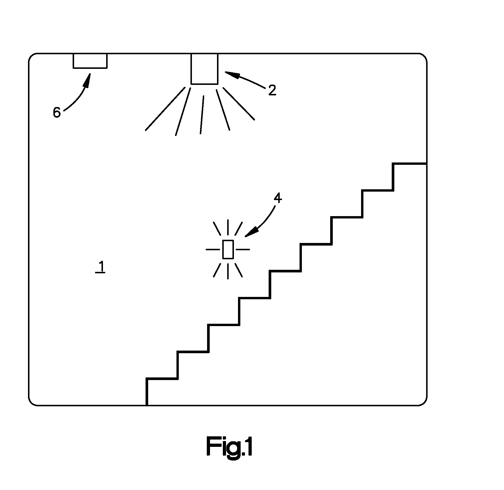
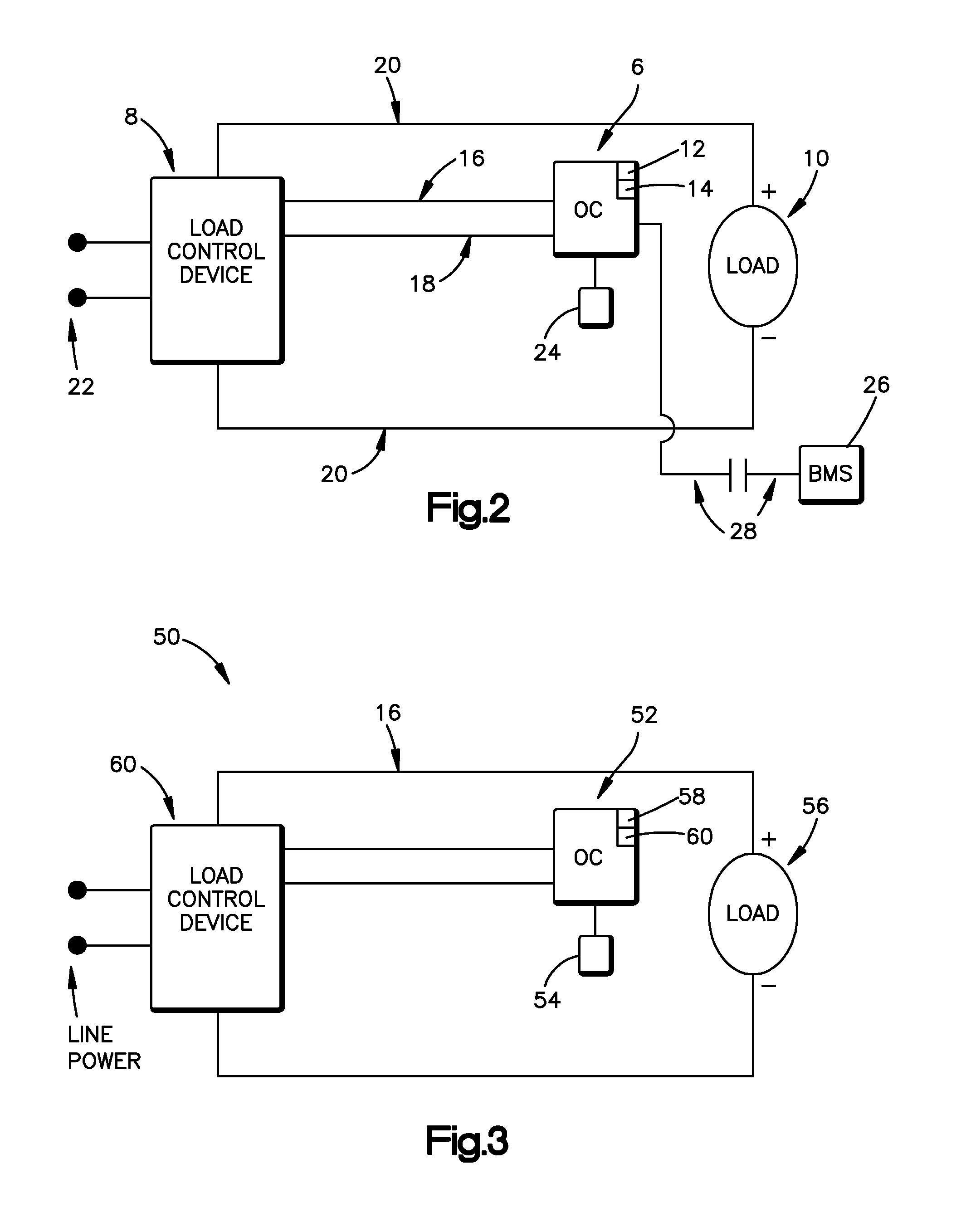
[0036]A system and method are disclosed for providing fail-safe operation of a lighting system so that primary lighting associated with an occupancy sensor will be energized in the event that a low level ambient “safety” light malfunctions. As will be appreciated, this functionality may be desirable for applications in which lighting systems may impact public safety. Examples of such applications may include, but are not limited to, lighting in public staircases, parking lots, parking ramps, or other areas where public safety may be compromised if a low level ambient “safety” lighting fails to energize, etc. The disclosed system and method may find application with a variety of different types of occupancy sensing technologies, load control devices, and loads.

[0037]Certain governmental life safety organizations have standards that require low level ambient lighting in stairwells and / or other public areas even when the stairwells are not occupied. For example, the National Fire Prote...


PUM


Abstract

A system and method provide fail-safe operation of a lighting system. A lighting level detector is used to obtain a baseline lighting level for a low-intensity light. If the detector measures less than the baseline level when an occupancy sensor determines the space is unoccupied, a high-intensity light is energized and an indication is provided to a user that the low-intensity light has failed. A method provides daylighting operation of a lighting system. An occupancy sensor can have Wi-Fi functionality to enable remote configuration of the sensor. A line voltage occupancy sensor can include an interface with low voltage devices. An occupancy sensor can include an integral interface to enable an external control system to override the sensor's normal logic under emergency conditions. An occupancy sensor can include an active temperature compensation feature. An occupancy sensor can also incorporate an automatically adjustable coverage area.

Description

CROSS-REFERENCE TO RELATED APPLICATIONS[0001]This is a divisional patent application of pending U.S. patent application Ser. No. 13 / 775,534, filed Feb. 25, 2013, titled “System and Method for Occupancy Sensing with Enhanced Functionality,” the entirety of which application is incorporated herein.FIELD OF THE DISCLOSURE[0002]The present disclosure relates generally to occupancy sensing systems, and more particularly to an improved system and method for occupancy sensing systems having enhanced functionality.BACKGROUND OF THE DISCLOSURE[0003]Occupancy sensors are designed to save energy by detecting the presence of a moving object in an area of coverage and switching a light source on and off depending upon the presence of the moving object. For example, when motion is detected within the area of coverage, the light source is turned on. Alternatively, when motion is not detected indicating that the area of coverage is not occupied, the light source is turned off after a predetermined ...

Claims


Application Information

Patent Timeline
Patent Type & Authority Applications(United States)
IPC IPC(8): H05B37/02
CPCH05B37/0272H05B37/0218H05B47/10H05B47/11H05B47/115H05B47/19H05B47/20Y02B20/40F21S8/006
Inventor LEINEN, RICHARD A.BALASUBRAMANIAN, JAIGANESHMORTON, JUSTINMUTHU, SUBRAMANIAN
Owner LEVITON MFG
Why Eureka
Try Eureka