Measurement module, electronic apparatus, power supply tap, power supply unit, and built-in measurement module

a measurement module and electronic equipment technology, applied in the direction of moving-iron instruments, coupling device connections, instruments, etc., can solve the problem of extra space for mounting the monitoring device in the apparatus, and achieve the effect of saving spa

Active Publication Date: 2014-12-25
CANON DENSHI KK
View PDF3 Cites 13 Cited by
  • Summary
  • Abstract
  • Description
  • Claims
  • Application Information

AI Technical Summary

Benefits of technology

[0007]Therefore, the present invention provides a measurement module for measuring a current, a voltage, or power and that can also achieve space saving.

Problems solved by technology

However, in the case of incorporating a monitoring device in each apparatus as described above, an extra space for mounting the monitoring device needs to be provided in the apparatus.

Method used


Image

  • Measurement module, electronic apparatus, power supply tap, power supply unit, and built-in measurement module
  • Measurement module, electronic apparatus, power supply tap, power supply unit, and built-in measurement module
  • Measurement module, electronic apparatus, power supply tap, power supply unit, and built-in measurement module

Examples


embodiment a

[0085]A module for measuring a current or power according to an embodiment (hereinafter, simply referred to as “measurement module 100”) will be described with reference to FIGS. 1 to 4.

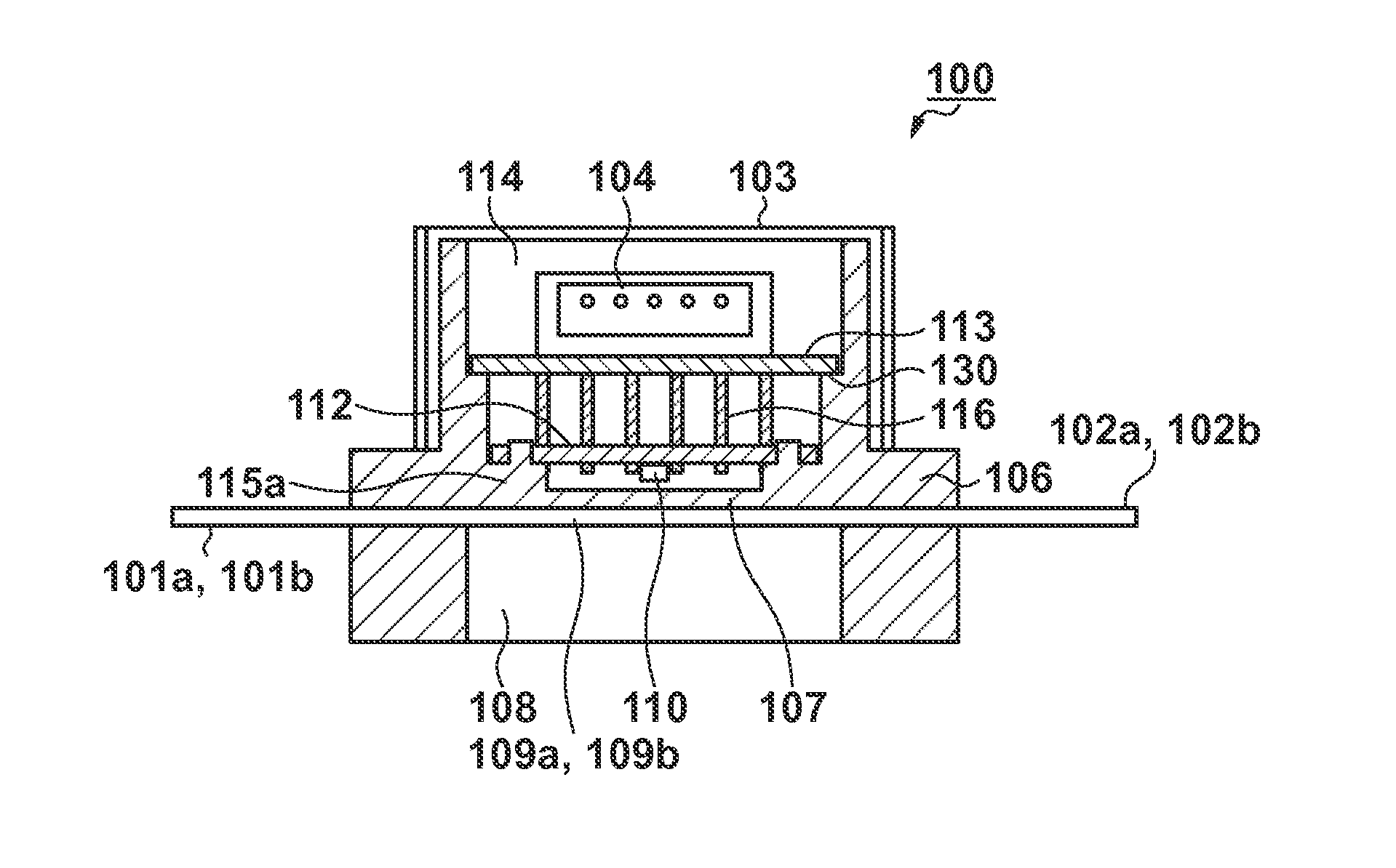
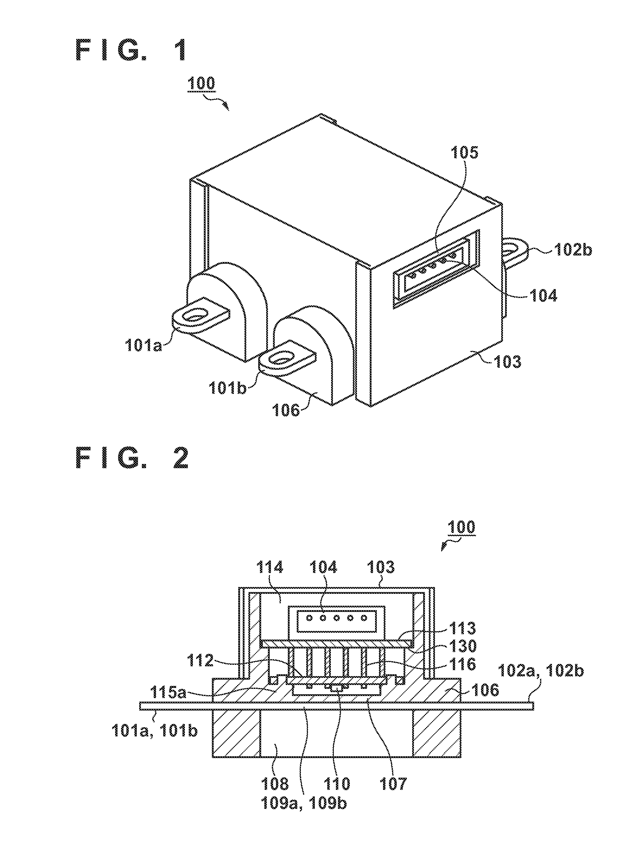
[0086]Referring to FIG. 1, a body 106 is formed of an insulating resin material as the raw material, and has an outer shape that is substantially rectangular parallelepiped. A pair of input terminals 101a and 101b to which a power supply cable or terminals of a measurement object are connected are provided on one side surface of the body 106. Output terminals 102a and 102b are provided on the opposite side. The body 106 is surrounded by a magnetic shield 103 except for the vicinity of the input terminals 101a and 101b and the output terminals 102a and 102b. In other words, the magnetic shield 103 is composed of six panels, and is substantially rectangular parallelepiped. As shown in FIG. 1, the magnetic shield 103 is provided with a window portion 105 for accessing a connector 104 provided inside the...

embodiment b

[0108]Embodiment B is characterized in that power can be more accurately detected than in Embodiment A by additionally providing a voltage detection circuit to the measurement module 100. As described in Embodiment A, power can be roughly evaluated by simply measuring a current. However, the voltage fluctuates depending on the load. For this reason, power cannot be accurately evaluated based on the current alone. Accordingly, detecting both a current and a voltage enables more accurate determination of power. In the following description, the same components as those in Embodiment A are given the same reference numerals, and the description is thereby simplified.

[0109]While the pair of input terminals 101a and 101b are connected to an external power supply such as a commercial AC power supply, it is often the case that which of the input terminals 101a and 101b serves as a HOT terminal or COLD terminal is not clearly defined. Therefore, in Embodiment B, the voltage is accurately det...

embodiment c

[0122]In Embodiment C, a description will be given of an exemplary application of the measurement modules 100 described in Embodiments A and B. By adopting the measurement modules 100 described in Embodiments A and B, it is possible to readily add functions of monitoring and controlling the power to the power supply unit, with little influence on the design of the power supply circuit.

[0123]For example, in the case of an image forming apparatus 200, which is an exemplary electronic apparatus, as shown in FIG. 9, a power supply unit is provided with the measurement module 100. The block diagram of the electronic apparatus is shown in FIG. 10. An AC inlet 202 is provided on a wall surface of the image forming apparatus 200. By connecting a power supply cord 203 from an external power supply to the AC inlet 202, power is supplied to a power supply circuit 201 of the image forming apparatus 200.

[0124]The measurement module 100 is mounted on the power supply circuit 201, and measures the...


PUM


Abstract

A measurement module includes a pair of input terminals, a pair of current paths connected to the pair of input terminals, and a pair of output terminals. A partition that is a non-magnetic insulating portion partitions an internal space of the measurement module into two spaces. Low-current components such as a magnetic detection element are disposed in a space different from a space in which the pair of current paths are housed. The presence of the partition allows the low-current components and the pair of current paths to be disposed close to one another, thus making it possible to reduce the size of the measurement module.

Description

[0001]This application is a continuation of International Patent Application No. PCT / JP2013 / 001533 filed on Mar. 8, 2013, and claims priority to Japanese Patent Application Nos. 2012-060949 filed on Mar. 16, 2012, and 2012-092470 filed on Apr. 13, 2012, the entire content of both of which are incorporated herein by reference.BACKGROUND OF THE INVENTION[0002]1. Field of the Invention[0003]The present invention relates to a measurement module for measuring a current, a voltage, or power, an electronic apparatus, a power supply tap, a power supply unit, and a built-in measurement module.[0004]2. Description of the Related Art[0005]In recent years, a reduction in CO2 emission and an increase in the efficiency of power utilization have become essential for suppressing global warming. For this reason, it is important to monitor a current or power within apparatuses such as home electric appliances, office automation equipment, and processing machinery so as to try to eliminate wasteful po...

Claims


Application Information

Patent Timeline
Patent Type & Authority Applications(United States)
IPC IPC(8): G01R19/00
CPCG01R19/0038H01R13/6683G01R15/207G01R21/06
Inventor KAWASE, MASAHIRO
Owner CANON DENSHI KK
Why Eureka
Try Eureka