Arrangement for optical measurements and related method

a technology of optical measurement and arrangement, applied in the field of optical measurement, can solve the problems of inability to accurately measure the topography of high-curvature surfaces associated with various objects, inability to meet the requirements of measurement accuracy, etc., to achieve good measurement accuracy, the effect of reducing the number of optical instruments

Active Publication Date: 2014-12-25
HELMEE IMAGING
View PDF17 Cites 19 Cited by
  • Summary
  • Abstract
  • Description
  • Claims
  • Application Information

AI Technical Summary

Benefits of technology

[0038]The provided technical arrangement further enables formation of various illumination patterns to be used for different measurement methods for both glossy (specular) and scattering (diffusive) surfaces of different target objects. Through the exploitation of photometric imaging even matte, i.e. highly scattering, surfaces may be analyzed and e.g. surface defects detected in connection with the present invention. The achieved accuracy of the measurements is good and the results are generally very reliable.
[0039]The provided arrange...

Problems solved by technology

Measuring the topography of high-curvature surfaces associated with various objects has in many occasions turned out difficult.
Traditional optical methods are limited to flat surfaces.
For small and flat surfaces e.g. interferometers can be used, but they are expensive, slow and provide unacceptable accuracy.
Different methods incorporating physical contact with the target objects are also often tedious, provide inferior horizontal resolution and even scratch or otherwise damage the potentially delicate surface under analysis.
Such drawbacks are rather comprehe...

Method used


Image

  • Arrangement for optical measurements and related method
  • Arrangement for optical measurements and related method
  • Arrangement for optical measurements and related method

Examples


Embodiment Construction

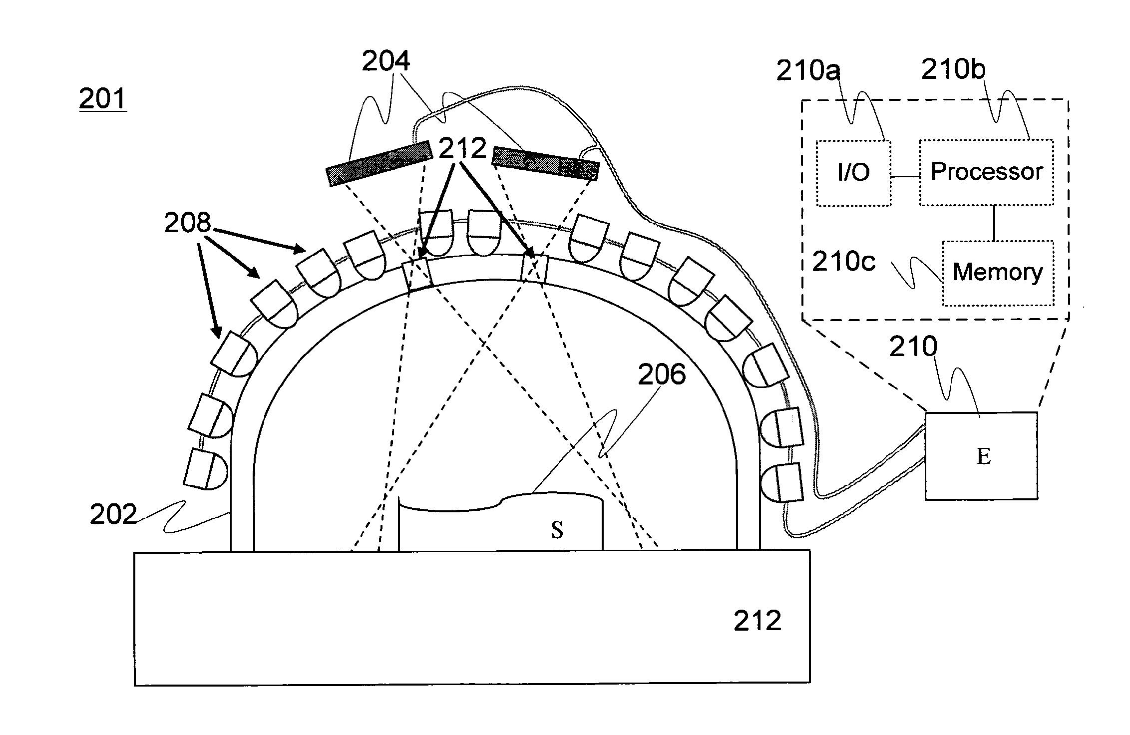
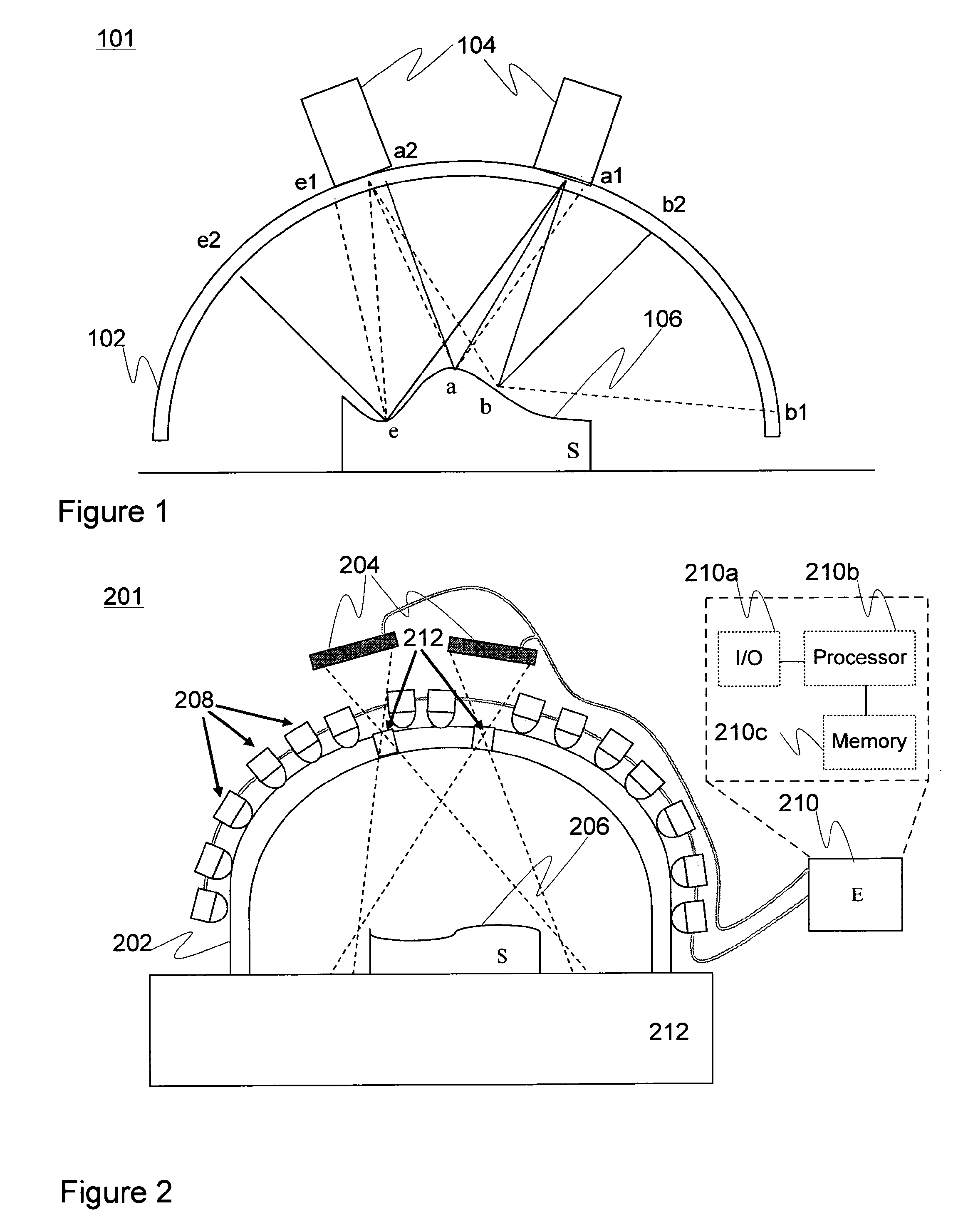
[0056]In FIG. 1, an embodiment of an illumination structure, essentially a dome structure, 102 is shown for projecting light provided by a number of embedded or at least optically coupled light sources towards a basically free-form target object, or ‘sample’, 106 disposed on a predetermined carrier surface, such as a ordinary table or sheet, and surrounded by the illumination structure 102 approximately hemispherically, i.e. above the level of the carrier surface. In some other embodiments, the object 106 could be hung e.g. from a string or be supported by a specific support structure such as a mount, depending on the nature of the illumination structure.

[0057]The object 106 may have been substantially centered relative to the illumination structure 102. The illumination structure 102 may generally bear a symmetrical shape as shown in the figure. Two light-sensitive sensor devices, or ‘imaging devices’, 104 such as digital cameras in many embodiments have been positioned relative to...


PUM


Abstract

An arrangement for optically measuring the surface of an optionally glossy target object, includes: a diffusive, semi-transparent illumination structure defining a hollow surface shape configured to surround the target object at least partially, the surface being further provided with at least two apertures, a number of light sources optically coupled to the diffusive illumination structure for illuminating the target object via the surface of the illumination structure, at least two imaging devices, each configured to image the target object via an aperture, and a control entity configured to instruct the number of light sources to form a sequence of predetermined illumination patterns illuminating the target object, to instruct the at least two imaging devices to obtain an image of the target object relative to each illumination pattern, and to derive, through the utilization of the patterns utilized and images obtained, a predetermined surface-related property of the target object.

Description

FIELD OF THE INVENTION[0001]Generally the present invention relates to optics. In particular, however not exclusively, the present invention concerns optical measurements for determining the topography of target objects.BACKGROUND[0002]Measuring the topography of high-curvature surfaces associated with various objects has in many occasions turned out difficult. Traditional optical methods are limited to flat surfaces. For small and flat surfaces e.g. interferometers can be used, but they are expensive, slow and provide unacceptable accuracy.[0003]Different methods incorporating physical contact with the target objects are also often tedious, provide inferior horizontal resolution and even scratch or otherwise damage the potentially delicate surface under analysis. Such drawbacks are rather comprehensible in the light of point-by-point scanning methods typically applied. Alternative machine vision—based arrangements do not perform too well either, particularly in connection with glos...

Claims


Application Information

Patent Timeline
IPC IPC(8): G01B11/24G01N21/956
CPCG01B11/24G01N2201/062G01N21/956G01B11/245G01B11/25G01C11/06G01N21/8806
Inventor KERANEN, HEIMOLEHTONEN, PETRI
Owner HELMEE IMAGING
Why Eureka
Try Eureka