
Polygon mirror assembly, light scanning unit employing polygon mirror assembly, and image forming apparatus

a technology of polygon mirrors and assembly, applied in the direction of mirrors, electrographic process apparatus, instruments, etc., can solve the problems of high manufacturing cost and difficulty in adjusting production volume, and achieve the effect of reducing deformation and suppressing optical performance degradation

Inactive Publication Date: 2014-12-25
HEWLETT PACKARD DEV CO LP
View PDF3 Cites 0 Cited by
  • Summary
  • Abstract
  • Description
  • Claims
  • Application Information

AI Technical Summary

Benefits of technology

The solution significantly reduces deformation of the polygon mirror's reflection surfaces during assembly, maintaining optical performance within permissible limits and enabling cost-effective mass production of plastic polygon mirrors.

Problems solved by technology

The polygon mirror assembly formed of the high-purity aluminum has problems such as a high manufacturing cost and difficulty in adjusting production volume.

Method used


Image

  • Polygon mirror assembly, light scanning unit employing polygon mirror assembly, and image forming apparatus
  • Polygon mirror assembly, light scanning unit employing polygon mirror assembly, and image forming apparatus
  • Polygon mirror assembly, light scanning unit employing polygon mirror assembly, and image forming apparatus

Examples


Embodiment Construction

[0025]Hereinafter, the present disclosure will now be described more fully with reference to the accompanying drawings, in which exemplary embodiments of the disclosure are shown. In the drawings, like reference numerals denote like elements, and a size of each component is exaggerated for convenience and clarity.

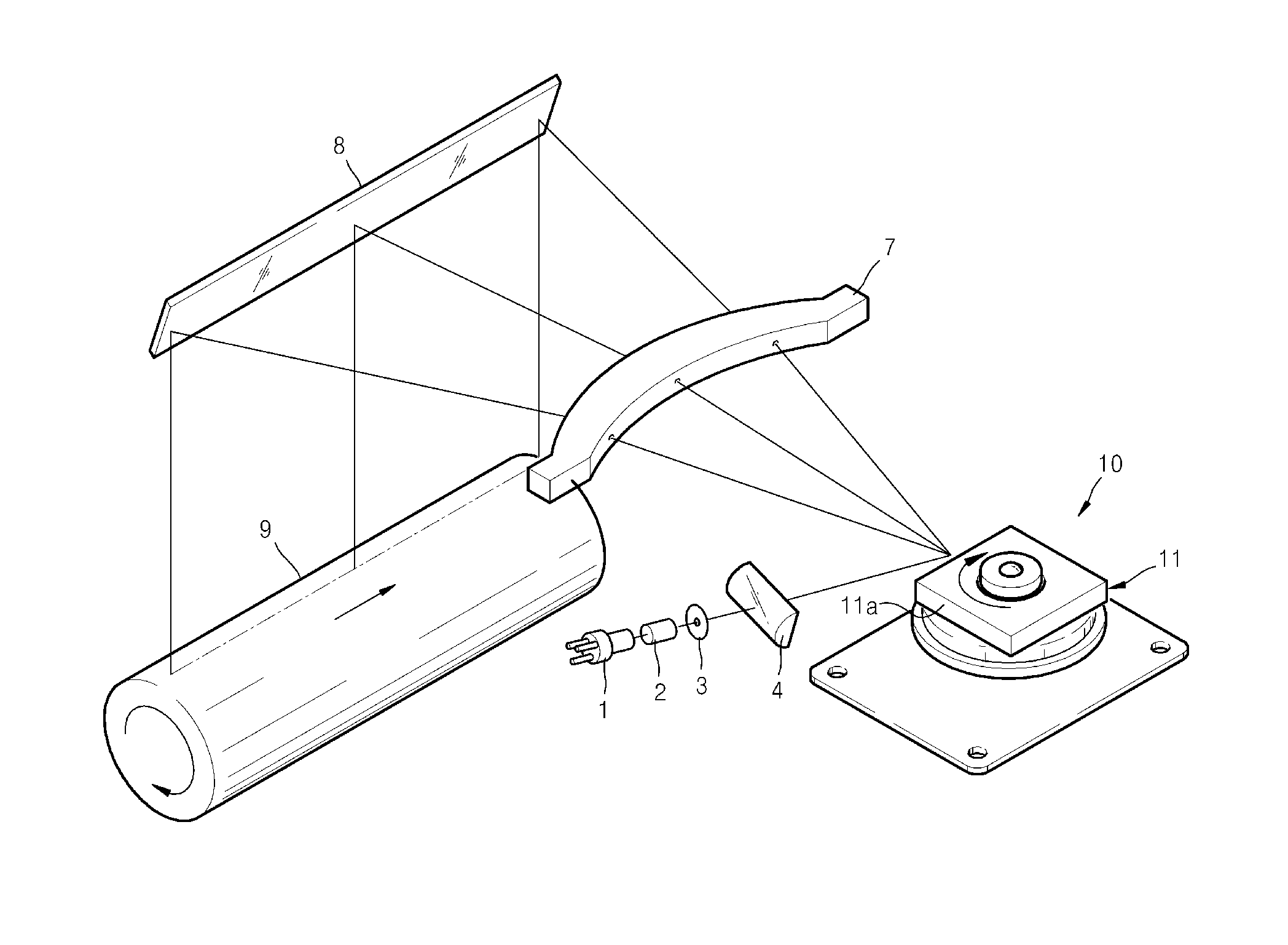
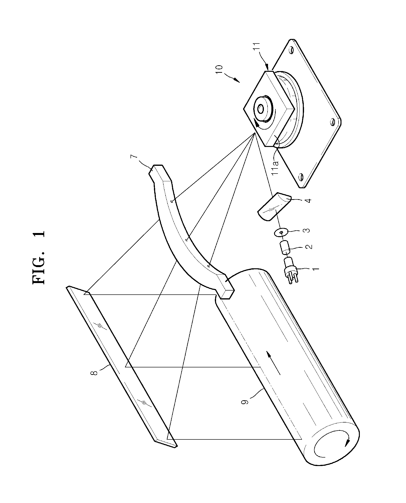
[0026]FIG. 1 is a schematic view of a light scanning unit employing a polygon mirror assembly 10, according to an embodiment of the present disclosure. FIG. 2 is a schematic cross-sectional view of the polygon mirror assembly 10 of the current embodiment.

[0027]Referring to FIG. 1, the light scanning unit includes a light source 1; the polygon mirror assembly 10 including a rotational polygon mirror 11, and a scanning lens 7.

[0028]The light source 1 emits a light beam and may be a semiconductor laser diode for emitting a laser beam. The light source 1 may emit a single light beam or a plurality of light beams. FIG. 1 illustrates the light source 1 emitting a single light bea...


PUM


Abstract

A polygon mirror assembly, a light scanning unit employing the polygon mirror assembly, and an image forming apparatus. The polygon mirror assembly includes a polygon mirror formed of a plastic material and having a plurality of reflection surfaces; and a motor unit to support and rotate the polygon mirror, where the polygon mirror is coupled to the motor unit by using an adhesive material.

Description

CROSS-REFERENCE TO RELATED APPLICATIONS[0001]This application is a continuation of U.S. application Ser. No. 13 / 200,827, filed on Oct. 3, 2011, which claims the benefit of Korean Patent Application No. 10-2010-0117524, filed on Nov. 24, 2010, in the Korean Intellectual Property Office, the disclosures of which are incorporated herein by reference in their entirety.BACKGROUND[0002]1. Field[0003]The present disclosure relates to a polygon mirror assembly, a light scanning unit employing the polygon mirror assembly, and an image forming apparatus, and more particularly, to a polygon mirror assembly including a plastic polygon mirror, a light scanning unit employing the polygon mirror assembly, and an image forming apparatus.[0004]2. Description of the Related Art[0005]Light scanning units that are employed in electrophotographic image forming apparatuses such as laser printers, digital photocopy machines, and facsimile machines deflect a light beam emitted from a light source to which ...

Claims


Application Information

Patent Timeline
Patent Type & Authority Applications(United States)
IPC IPC(8): G03G15/043G02B26/12
CPCG02B26/129G03G15/043G02B5/09G02B26/12
Inventor LIM, HEON-HEEYOO, JAE-HWANCHUN, JIN-KWONKU, JONG-WUK
Owner HEWLETT PACKARD DEV CO LP
Learn More