
Chromatography pipette tip

a technology of chromatography and pipette, which is applied in the direction of pipettes/pipettes, laboratory equipment, chemistry apparatus and processes, etc., can solve the problems of large variance in results, unreliable start-up, and individual volumes of sample liquid that require different lengths of time,

Inactive Publication Date: 2014-12-25
CYBIO AG
View PDF6 Cites 6 Cited by
  • Summary
  • Abstract
  • Description
  • Claims
  • Application Information

AI Technical Summary

Benefits of technology

This patent describes a device that allows for sealed connections between two vessels in a chromatography system. The device includes a first vessel channel and a second vessel channel, with a second valve to seal the first vessel from the environment. The second vessel can be raised and lowered along the first vessel axis, and its outer wall can contact the bottom surface of the first vessel to seal the remaining space from the environment. This design eliminates the need for additional sealing means when using chromatography pipette tips. The device also allows for the suspension of multiple chromatography pipette tips in a magazine for connection to a multipipettor. The technical effects of this design include improved sealing, easier handling, and enhanced flexibility for chromatography systems.

Problems solved by technology

Particularly when the sample liquid runs through the reaction matrix due only to the earth's gravitational pull acting upon it, the problem may arise that individual volumes of sample liquid require different lengths of time to pass through a column when carrying out processes in parallel.
Arrangements in which a plurality of volumes of sample liquid are treated in parallel by gravity, e.g., reaction matrixes are arranged in an array, frequently exhibit unreliable start-up, i.e., the sample liquid does not begin to flow through the respective reaction matrix at the same time, e.g., owing to wetting problems and disparate throughflow times (retention times) which can occur even as a result of very slight differences in the packing of the reaction matrixes (density, amount, spatial distribution of the separation material).
In experimental or diagnostic applications in which a plurality of identically handled volumes of a sample liquid are to be compared with each other or with a reference, retention times of varying length can lead to large variances in results, to errors or even to sample failures.
A possible alteration in packing density and in the wetting of the reaction matrix resulting from the centrifugal forces and the high operating costs exclude repeated use in partial steps and particularly automated procedures.
In a further embodiment of the pipette tip, dispensing is not carried out via the intake and outlet area; therefore, this embodiment is not suitable for drawing in and dispensing one or more liquids multiple times from the same sample vessel or from identically designed sample vessels.
The compressibility of the relatively large air buffer, which also limits the maximum possible pressure by which the liquid can be expelled from the pipette tips, can be a drawback with regard to dispensing liquid in an exactly identical fashion via all of the pipette tips.
These are used for dispensing particularly thick materials, e.g., gels, and in association with contamination-protected pipetting because they do not allow the sample liquid to enter the pipette.
Accordingly, pipette tips for positive displacement pipettors are comparatively more complicated and, consequently, more expensive and are therefore used less often than pipette tips for air displacement pipettes for routine laboratory work.
Both of the common pipette tips mentioned above are basically unsuitable for applications in which a liquid may only run through the pipette tip in one flow direction; for this reason, they appear suitable for chromatography only under certain conditions if at all.
Therefore, a highly precise, identical separation of the sample constituents is not possible when processes are carried out parallel in time.
If the separation process is to be carried out over a number of separation steps, the sample liquid must be added anew to the reaction matrixes for each separation step, which could require breaking the seal between the column and pipetting device each time, and the disadvantages which were described above can occur.

Method used


Image

  • Chromatography pipette tip
  • Chromatography pipette tip
  • Chromatography pipette tip

Examples


Embodiment Construction

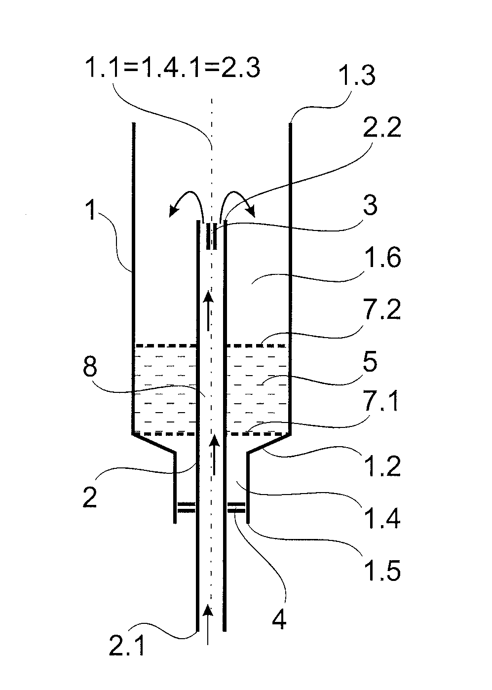
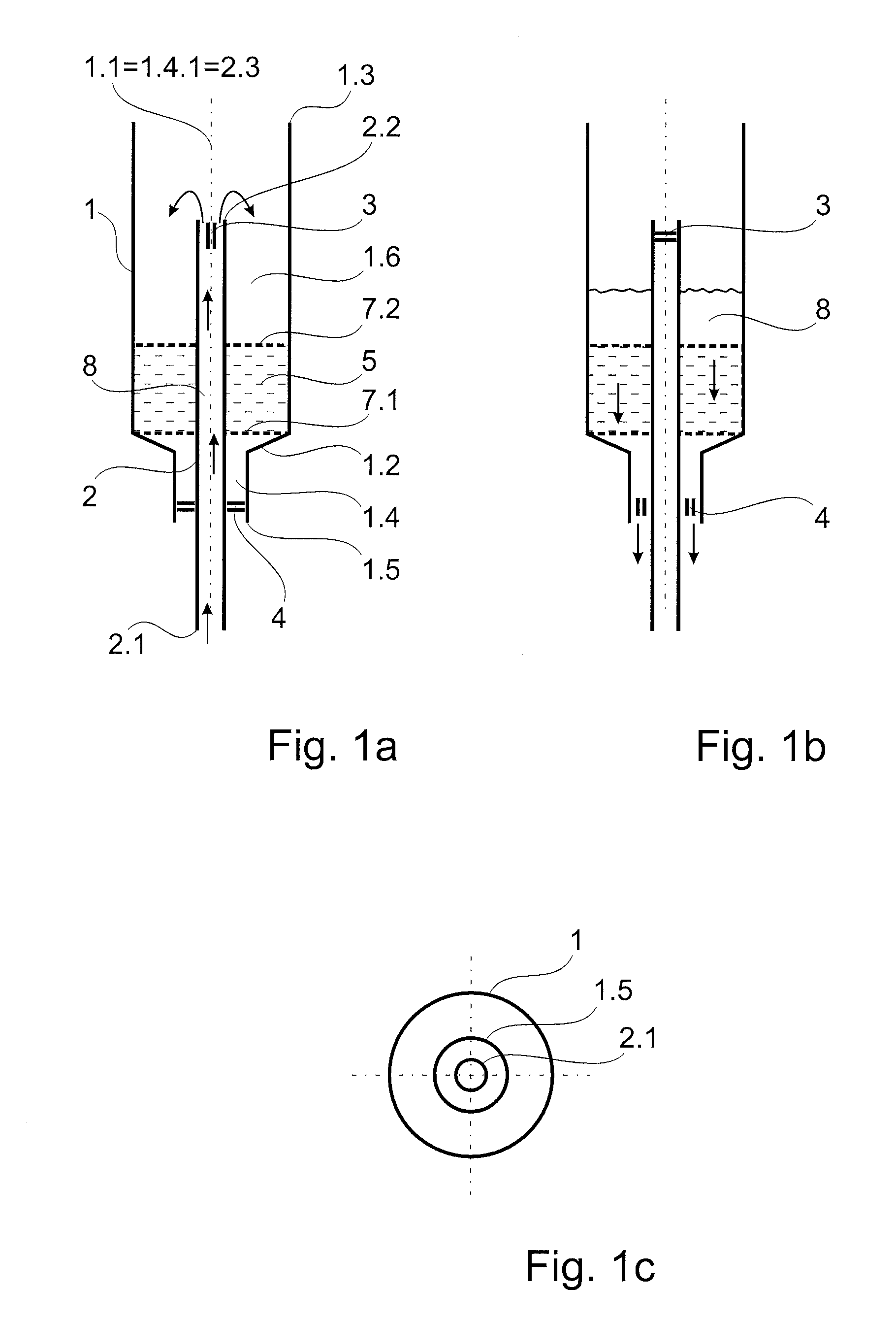
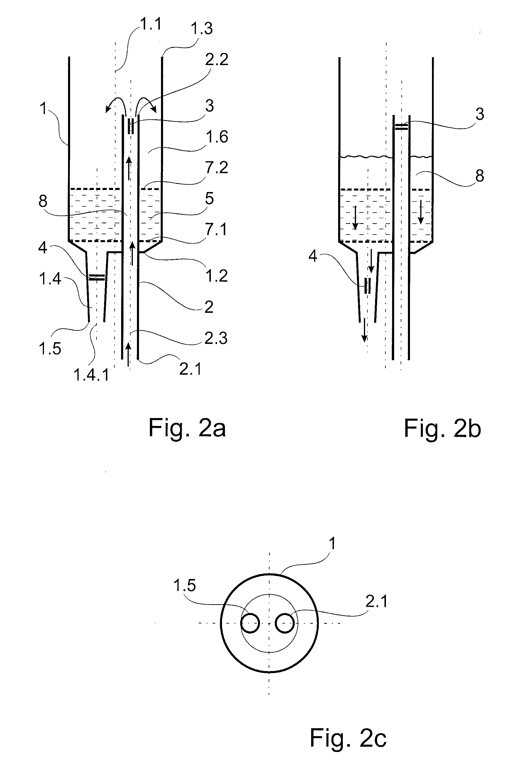
[0058]A chromatography pipette tip according to the invention, i.e., a pipette tip which is provided for carrying out methods of chromatography in conjunction with metering aids such as pipettors, as can be seen in all of the schematic diagrams of the embodiment examples, basically has a first vessel 1 with a first vessel axis 1.1. Like conventional pipette tips, the first vessel 1 is preferably cylindrical, conical or has a combination of cylindrical and conical portions. It has a base surface 1.2 which is preferably conical and an end 1.3 which is located opposite the base surface and which serves as a mounting lip so that it can be connected with a metering aid. An elongate first vessel channel 1.4 with a channel axis 1.4.1 opening into a bottom orifice 1.5 of the first vessel is formed in the base surface 1.2. The bottom orifice 1.5 of the first vessel can preferably be sealed from the environment. The sealing is carried out by means of a second valve 4 in most of the embodiment...


PUM


Abstract

Chromatography pipette tip having a first vessel and a second vessel which is open at two opposite ends and which, in each instance, has a bottom orifice via which a sample liquid can either be sucked in or expelled. The two vessels are fluidically and sealably connected to one another. A reaction matrix is arranged in one of the two vessels, through which reaction matrix the sample liquid is pushed by means of a pipettor to which the chromatography pipette tip is connected when used as intended. The sample liquid is drawn in and dispensed in opposite directions by the chromatography pipette tip and flows through the reaction matrix only in one direction.

Description

RELATED APPLICATIONS[0001]The present application claims priority benefit of German Application No. DE 10 2013 106 534.1 filed on Jun. 21, 2013, the contents of which is incorporated by reference in its entirety.FIELD OF THE INVENTION[0002]The invention is directed to a chromatography pipette tip such as is known generally in Utility Model DE 297 18 238 U1.BACKGROUND OF THE INVENTION[0003]The concept of chromatography covers a large number of methods for the separation of sample constituents, e.g., macromolecules, ions, agglomerations, chelates, particles or combinations thereof, which are in the form of a solution or suspension in a liquid and form a mobile phase with the liquid. The basic principle behind all of these separation methods is that the mobile phase (referred to hereinafter as “sample liquid” for the sake of simplicity) is guided past or through a stationary phase. In so doing, interactions occur between the individual sample constituents and the stationary phase, whic...

Claims


Application Information

Patent Timeline
IPC IPC(8): B01L3/02B01D15/22
CPCB01D15/22B01L3/0275B01L2300/0681B01L2400/0605
Inventor SAMMLER, GUENTHERBUESCHEL, MARIOTAUTKUS, BAERBELRHODE, HEIDRUNWENDLER, SINDY
Owner CYBIO AG
Learn More