
Cutting-in, standoff, illumination system and method

Inactive Publication Date: 2014-12-25
BAILEY JOHN D
View PDF3 Cites 0 Cited by
  • Summary
  • Abstract
  • Description
  • Claims
  • Application Information

AI Technical Summary

Benefits of technology

This patent describes a method and device for securing a light to a brush to make it easier to illuminate the edge of the brush during cutting-in processes. The device includes a securement mechanism, such as hook-and-loop fasteners or a standoff, to keep the light at a proper distance from the brush and provide a central axis of light that is offset from an outer surface of the brush. This allows for better precision and visibility during cutting-in tasks. Overall, the invention improves the ability of users to see and work with their brushes in low-light settings.

Problems solved by technology

For residential and commercial painting of interior surfaces, boundaries are the most difficult and time consuming.
Unfortunately, light is a perennial problem.
Even in daylight, or room lighting system light, and even with specialized flood lighting set up by a painter, light is a problem.
The specific problem is that a painter is close to a brush, the brush is against the wall, and everything culminates at the wall on the edge of the brush as painting continues.
Moreover, bright working lights result in reflections from a wall, which tend to close down the pupils of a painter.
Accordingly, having adjusted to increased ambient light, the eyes can no longer properly distinguish the fine distinctions in the shadowed region near the tip of the brush.

Method used


Image

  • Cutting-in, standoff, illumination system and method
  • Cutting-in, standoff, illumination system and method
  • Cutting-in, standoff, illumination system and method

Examples


Embodiment Construction

[0043]It will be readily understood that the components of the present invention, as generally described and illustrated in the drawings herein, could be arranged and designed in a wide variety of different configurations. Thus, the following more detailed description of the embodiments of the system and method of the present invention, as represented in the drawings, is not intended to limit the scope of the invention, as claimed, but is merely representative of various embodiments of the invention. The illustrated embodiments of the invention will be best understood by reference to the drawings, wherein like parts are designated by like numerals throughout.

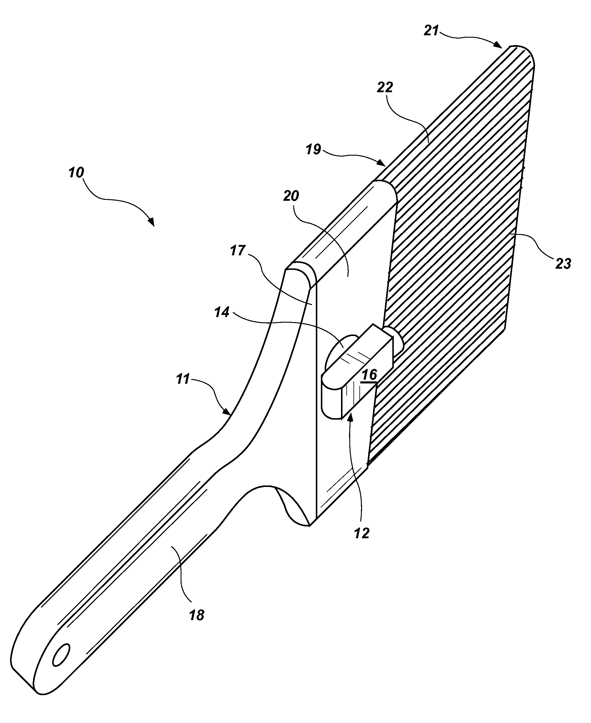
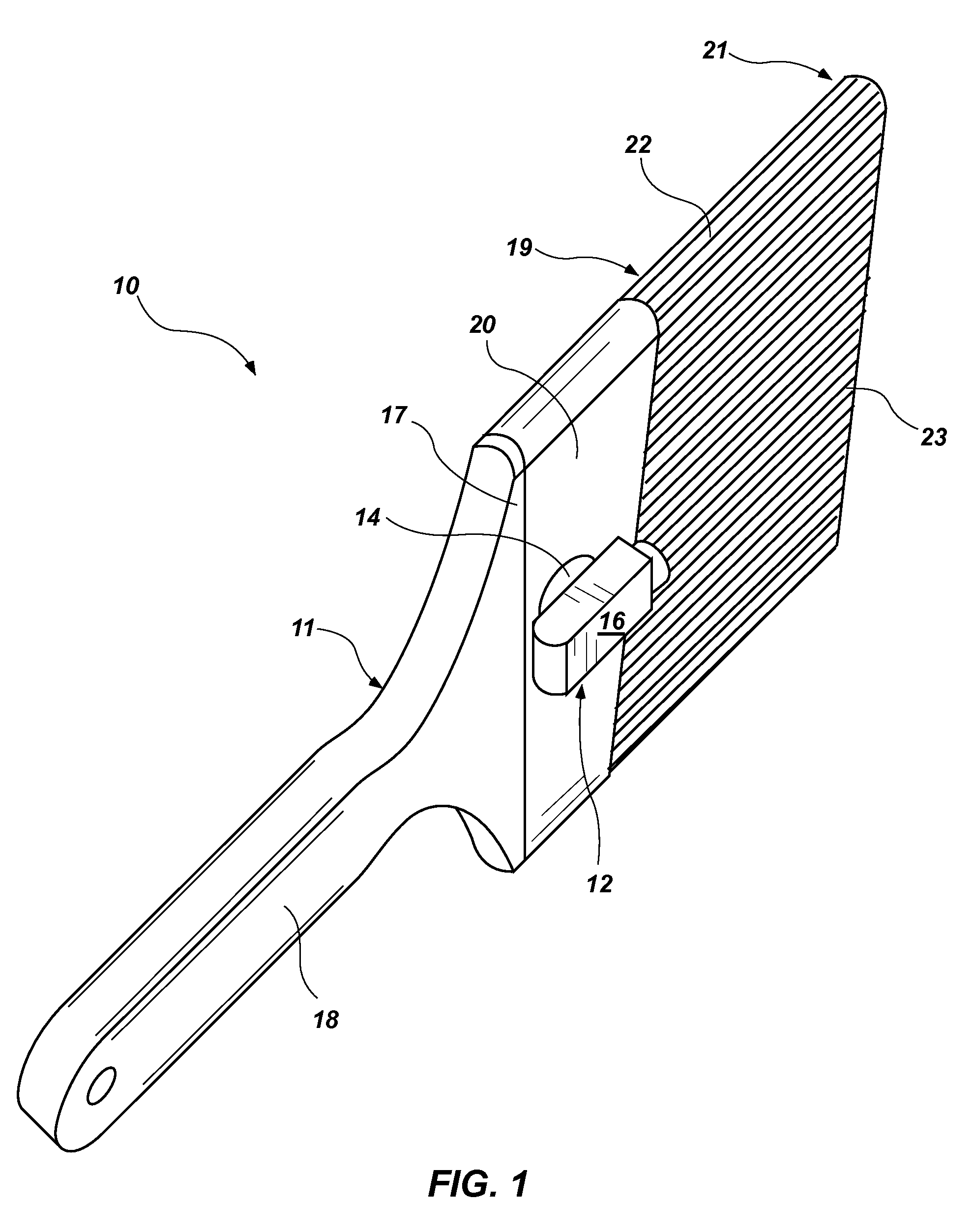
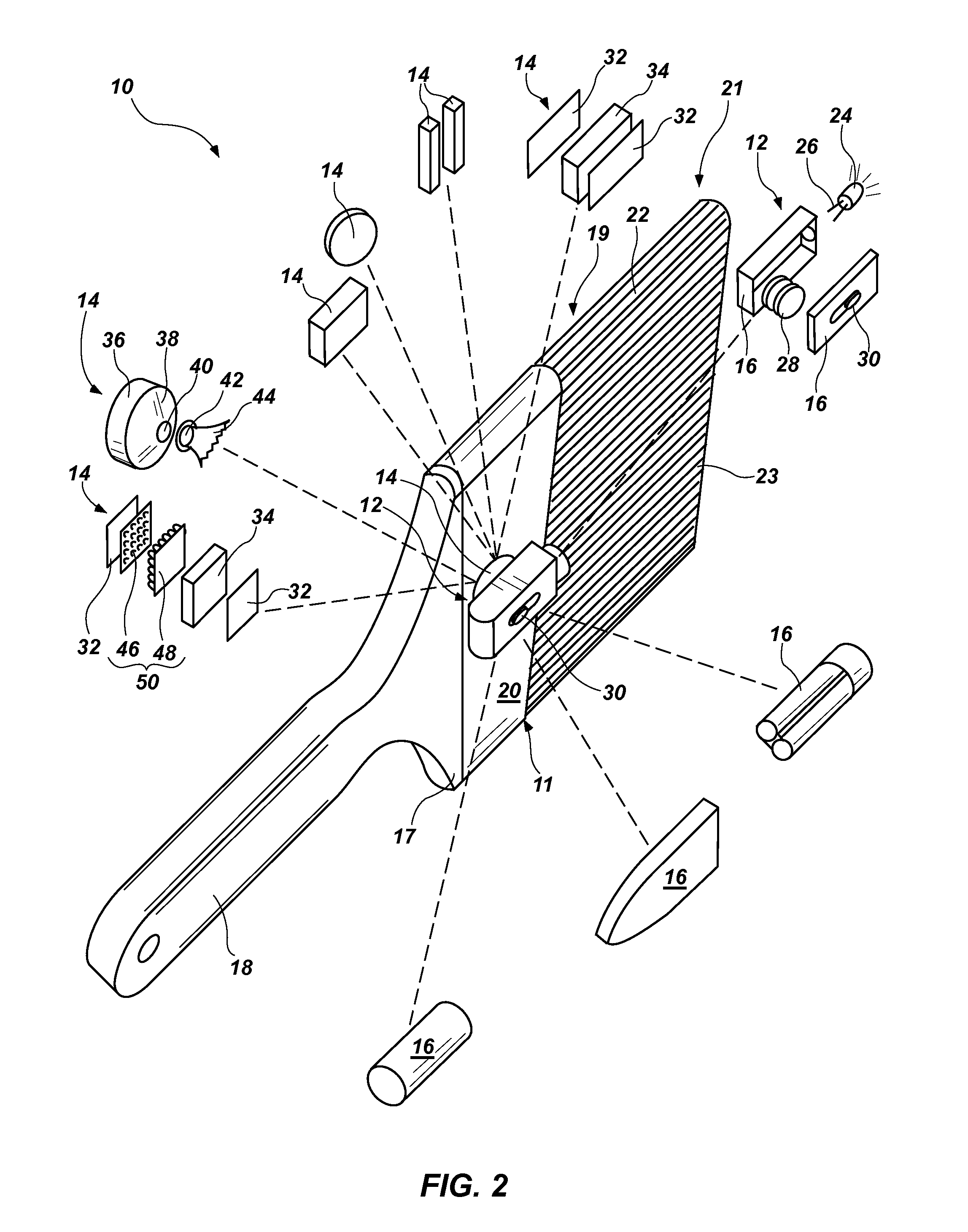
[0044]Referring to FIG. 1, while referring generally to FIGS. 1 through 4, an apparatus 10 in accordance with the invention may include a paintbrush 11 provided with a light assembly 12. In the illustrated embodiment, a paintbrush may be of any particular type, but is most applicable for the invention if it contains bristle or i...


PUM

PropertyMeasurementUnit
Poweraaaaaaaaaa
Dimensionaaaaaaaaaa
Distanceaaaaaaaaaa

Abstract

An apparatus and method provide an adjustable, aimed, lighting system that may be selectively secured to and removed from the ferrule of a paintbrush for illuminating the edge of the bristles during a cutting-in process. The light may be moved as appropriate, and may be aimed to ride with the brush, thus illuminating directly at the edge where paint is being deposited. Thus, precise deposition of paint may be done in spite of the shadows cast by the body of the painter and the bulk of the brush during much of such cutting-in procedures.

Description

RELATED APPLICATIONS[0001]This application claims the benefit of U.S. Provisional Patent Application Ser. No. 61 / 838,930, filed Jun. 25, 2013, which is hereby incorporated by reference in its entirety.BACKGROUND[0002]1. Field of the Invention[0003]This invention relates to painting and, more particularly, to novel systems and methods for lighting a work area for a paintbrush during a cutting-in operation.[0004]2. Background Art[0005]For residential and commercial painting of interior surfaces, boundaries are the most difficult and time consuming. For example, a window may have a stained wood color, as to the seal and frame, while the surrounding wall is painted a particular color of the room. Although masking is possible, many commercial painters will simply “cut-in” along a boundary line, such as an internal corner, external corner, boundary line, or the like.[0006]Cutting-in is the process of pressing the bristles of a paintbrush sideways flat against a surface being painted, whil...

Claims


Application Information

Patent Timeline
IPC IPC(8): A46B15/00A46B3/12B05D1/28B44D3/00
CPCA46B15/0036B05D1/28A46B3/12B44D3/00Y10T29/49826Y10T29/49947
Inventor BAILEY, JOHN D.
Owner BAILEY JOHN D
Learn More