Power sharing for a locomotive consist

a technology of power sharing and locomotives, applied in the direction of process and machine control, vehicle position/course/altitude control, instruments, etc., can solve the problems of system limitation, system may still be problematic, and lack of capability

Inactive Publication Date: 2014-12-25
PROGRESS RAIL SERVICES
View PDF2 Cites 13 Cited by
  • Summary
  • Abstract
  • Description
  • Claims
  • Application Information

AI Technical Summary

Problems solved by technology

Although the system of the '588 patent may have improved communication between multiple locomotives in a consist, the system may still be problematic.
In particular, the system may be limited to communicating power operating requirements and control signals to each locomotive in a consist, but without the capability of actually sharing electrical power generated by power sources on each of the locomotives.

Method used


Image

  • Power sharing for a locomotive consist
  • Power sharing for a locomotive consist
  • Power sharing for a locomotive consist

Examples


Embodiment Construction

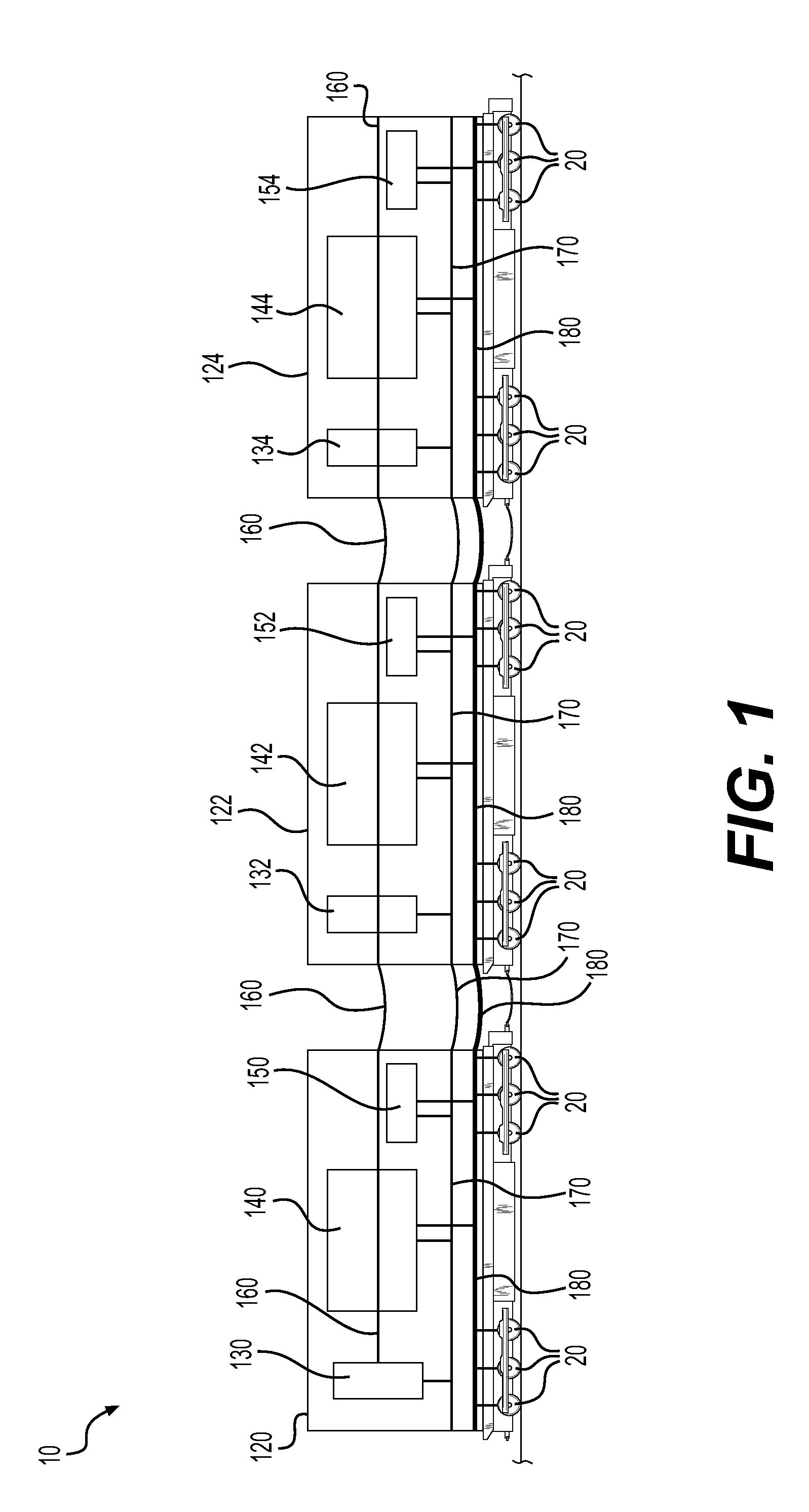
[0011]FIG. 1 illustrates an exemplary locomotive power sharing system 10 in a train consist having a lead locomotive 120, a first trailing locomotive 122, and a second trailing locomotive 124. In alternative implementations, a locomotive other than locomotive 120 may be the lead locomotive of the consist. In some implementations, additional or fewer locomotives may be included within the consist. Each locomotive 120, 122, 124 may include one or more power sources. In the exemplary implementation illustrated in FIG. 1, each locomotive includes a prime mover power source 140, 142, 144, respectively, and an auxiliary power source 150, 152, 154, respectively. Prime mover power sources 140, 142, 144 may each include a relatively large diesel engine (e.g., a 3300 HP diesel engine) and an alternator or generator. This diesel-electric power source converts the energy derived from diesel fuel into electrical power that may then be provided to an electrical power bus 180. Auxiliary power sour...


PUM


Abstract

A method of sharing power between locomotives in a consist may include receiving a power demand signal at a control computer on one of the locomotives, with the power demand signal indicative of a total power output requirement for the consist. The control computer may determine an amount of available power on an electrical power bus running through all of the locomotives in the consist, and the power generating capacity of all power sources that are electrically coupled to the electrical power bus. One or more power sources on any one of the locomotives in the consist may be activated to provide electrical power to the electrical power bus for use by a load on a different one of the locomotives in the consist.

Description

TECHNICAL FIELD[0001]The present disclosure relates generally to power sharing and, more particularly, to power sharing for a locomotive consist.BACKGROUND[0002]A train consist often includes a lead locomotive and at least one trailing locomotive. The lead locomotive, although generally located at the leading end of the consist, can alternatively be located at any other position along its length. The lead locomotive generates operator and / or autonomous control commands directed to components of the lead and trailing locomotives. A typical locomotive of a consist will have a prime mover power source that includes a diesel engine and an alternator or generator that converts rotational output of the diesel engine into electrical power. The term “prime mover” is generally used to refer to the source of power used primarily for generating a tractive effort used in moving the vehicle. A prime mover power source may also provide power for parasitic or auxiliary loads that do not contribute...

Claims


Application Information

Patent Timeline
Patent Type & Authority Applications(United States)
IPC IPC(8): B61C17/12B61C7/04
CPCY02T90/124Y02T90/16B61C7/04B61C17/12B60W20/10B60L15/32B61C5/00Y02T30/00Y02T90/12
Inventor KRAL, JOHN FRANKLINBIAGINI, DOUGLAS MICHAEL
Owner PROGRESS RAIL SERVICES
Why Eureka
Try Eureka