Heat-Transfer Device

a technology of heat-transfer device and nano-particle, which is applied in the direction of lighting and heating apparatus, tubular elements, stationary conduit assemblies, etc., can solve the problem of difficulty in obtaining the heat-transfer enhancement effect of nano-particle porous layer sufficiently, and achieve the effect of heat-transfer enhancement effect of micro-porous layer

Inactive Publication Date: 2015-01-01
HITACHI LTD
View PDF9 Cites 12 Cited by
  • Summary
  • Abstract
  • Description
  • Claims
  • Application Information

AI Technical Summary

Benefits of technology

[0009]The invention allows the heat-transfer enhancement effect of the mi

Problems solved by technology

This technique, thus, suffers difficulty in obtaining the heat-transfer enhancement effect of the nano-particle porous layer sufficiently due to an increased thickne

Method used


Image

  • Heat-Transfer Device
  • Heat-Transfer Device
  • Heat-Transfer Device

Examples


first embodiment

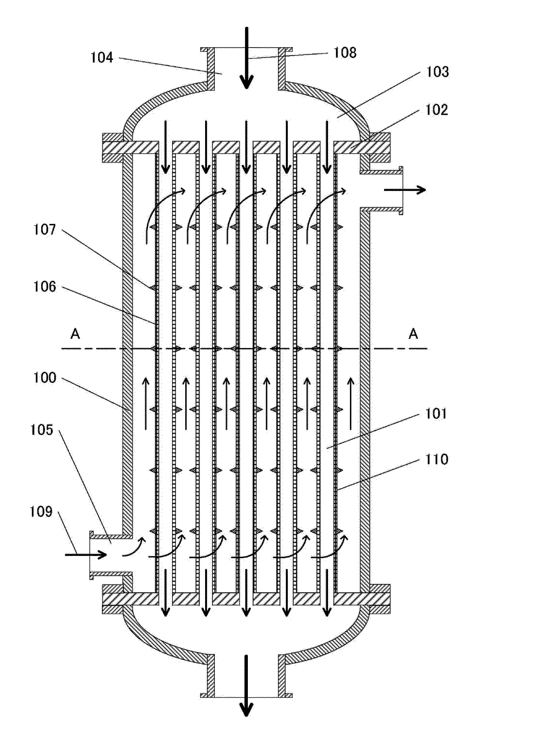
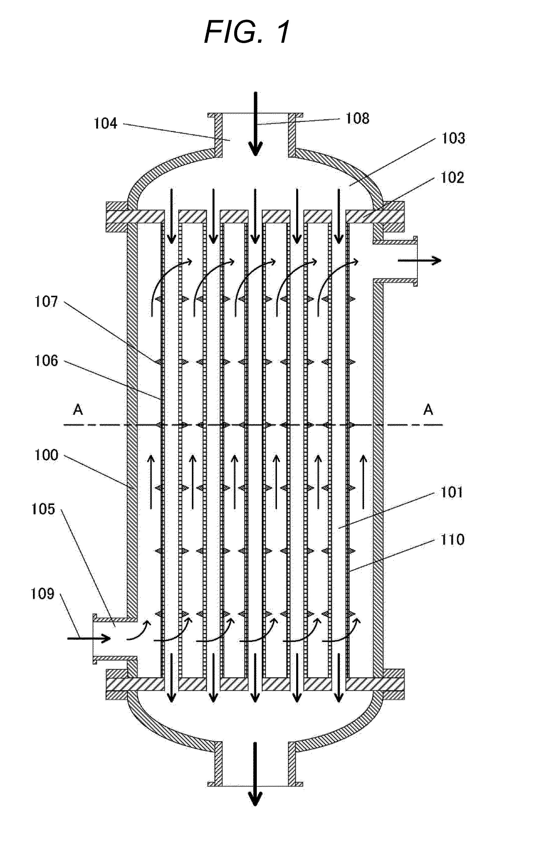
[0019]A first embodiment of the invention is a shell and tube heat exchanger with the heat-transfer device applied. This embodiment is capable of improving heat-transfer performance even under conditions of low flow velocities of a fluid used for heat exchange, in comparison with a conventional shell and tube heat exchanger.

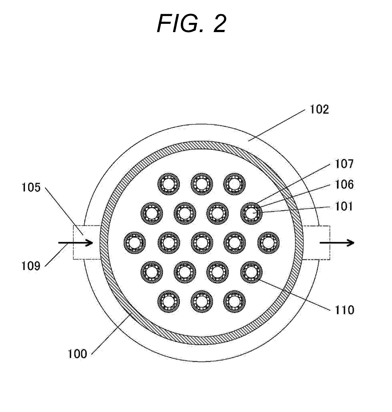
[0020]FIG. 1 is a structure diagram of the shell and tube heat exchanger according to the embodiment. A shell 100, which is circular or polygonal, is provided on both sides with tube plates 102 for supporting heat transfer tubes 101. The tube plates 102 each have a large number of holes arranged therein in a zigzag manner to allow the passage of the heat transfer tubes 101. The heat transfer tubes 101 pass through these tube holes to be fixed to the tube plates 102 at both sides. The heat transfer tubes 101 are made with a metal having high thermal conductivity, such as aluminum and copper. The heat transfer tubes 101 may be made with SUS. A vapor 108, which is a...

second embodiment

[0029]A second embodiment is a shell and tube heat exchanger with the heat-transfer device applied. This embodiment is capable of improving the heat-transfer performance even under conditions of low flow velocities of a fluid used for heat exchange, in comparison with a conventional shell and tube heat exchanger. The embodiment can also curb vibration of heat transfer tubes that accompanies the condensation of vapor.

[0030]FIG. 4 is a structure diagram of the shell and tube heat exchanger according to the second embodiment. FIG. 5 is a sectional view taken along line A-A of FIG. 4. The shell and tube heat exchanger in FIG. 4 will now be described, with an omission of parts indicated with the same reference numerals and having similar functions with those in the arrangement described in FIG. 1.

[0031]A micro porous layer 110 described in the first embodiment is formed on the outer surface of each heat transfer tube 101 to enhance heat transfer. A plurality of heat-transfer enhancing st...


PUM


Abstract

The invention includes a micro porous layer and a plurality of heat-transfer enhancing structures on a surface of the heat transfer tube in contact with the cold fluid. The heat-transfer enhancing structures have a height H that satisfies a relationship to a flow characteristic length D of 0.05>H/D≧0.01, and a relationship to an installation clearance L between the heat-transfer enhancing structures in a flow direction of 40<L/H≦300.

Description

BACKGROUND OF THE INVENTION[0001]1. Field of the Invention[0002]The present invention relates to a heat-transfer device.[0003]2. Description of the Related Art[0004]Heat exchangers, which allow two fluids at different temperatures to perform heat exchange, and heaters and coolers of fluids often use convective heat transfer, which is a form of heat transfer that uses heat transportation by flow. In the convective heat transfer, thermal energy is transferred from a heating or cooling surface through a heat conduction layer, a transition layer, and a convection layer to a fluid. The heat conduction layer is a fluid layer formed in a very thin region on the heating or cooling surface. In this layer, heat conduction due to fluid molecular diffusion is dominant rather than the heat transportation by flow. The heat conduction layer has a thickness determined by the Reynolds number Re, which is a dimensionless number representing the ratio of inertial forces to viscous forces in a flow, an...

Claims


Application Information

Patent Timeline
IPC IPC(8): F28F1/00F28D1/06F28D1/00
CPCF28D1/06F28D1/00F28F1/00F28F13/12F28F13/185F28F13/06F28F13/187F28D7/16
Inventor TAMURA, AKINORIKAWAMURA, TOSHINORIKITOU, KAZUAKINAKANO, HIROSHI
Owner HITACHI LTD
Why Eureka
Try Eureka