Threaded joint for pipes

a threaded joint and pipe technology, applied in the direction of hose connections, screw threaded joints, mechanical equipment, etc., can solve the problems of deteriorating the gas tightness of the threaded joint, clogging of the groove, and unable to function as a leakage path, so as to facilitate the formation of the coating

Active Publication Date: 2015-01-01
NIPPON STEEL CORP +1
View PDF8 Cites 19 Cited by
  • Summary
  • Abstract
  • Description
  • Claims
  • Application Information

AI Technical Summary

Benefits of technology

[0024]It is advantageous to form the solid lubricating coating on the entire surface of the pin and / or box in order to facilitate the formation of the coating. The surface of a pin or a box means the surface facing the other member and generally extends from its threaded portion to the shoulder surface.

Problems solved by technology

If this occurs, due to the fact that the fluidity of the solid lubricating coating is much lower than that of liquid lubricating grease, the grooves are clogged and cannot function as a leak path.
As a result, the pressure in the non-contacting region 13 is increased, resulting in a deterioration of the gas tightness of the threaded joint which is achieved by the sealing surfaces.

Method used


Image

  • Threaded joint for pipes
  • Threaded joint for pipes
  • Threaded joint for pipes

Examples


example

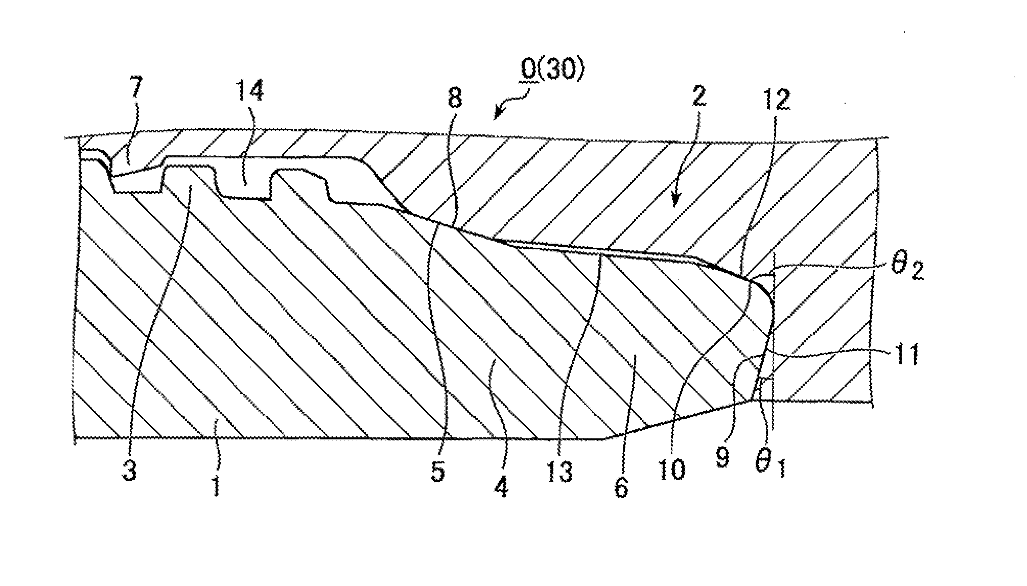
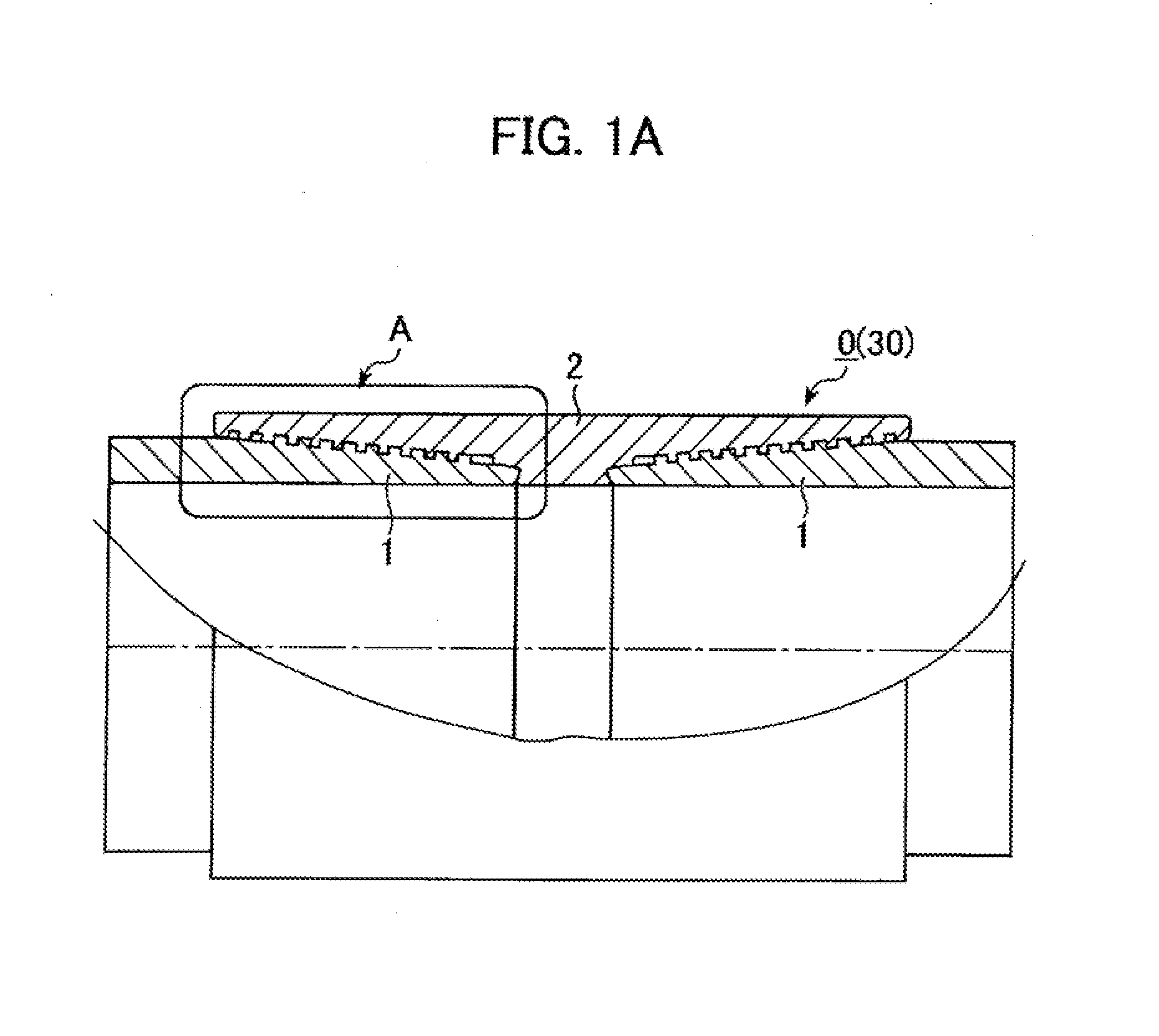
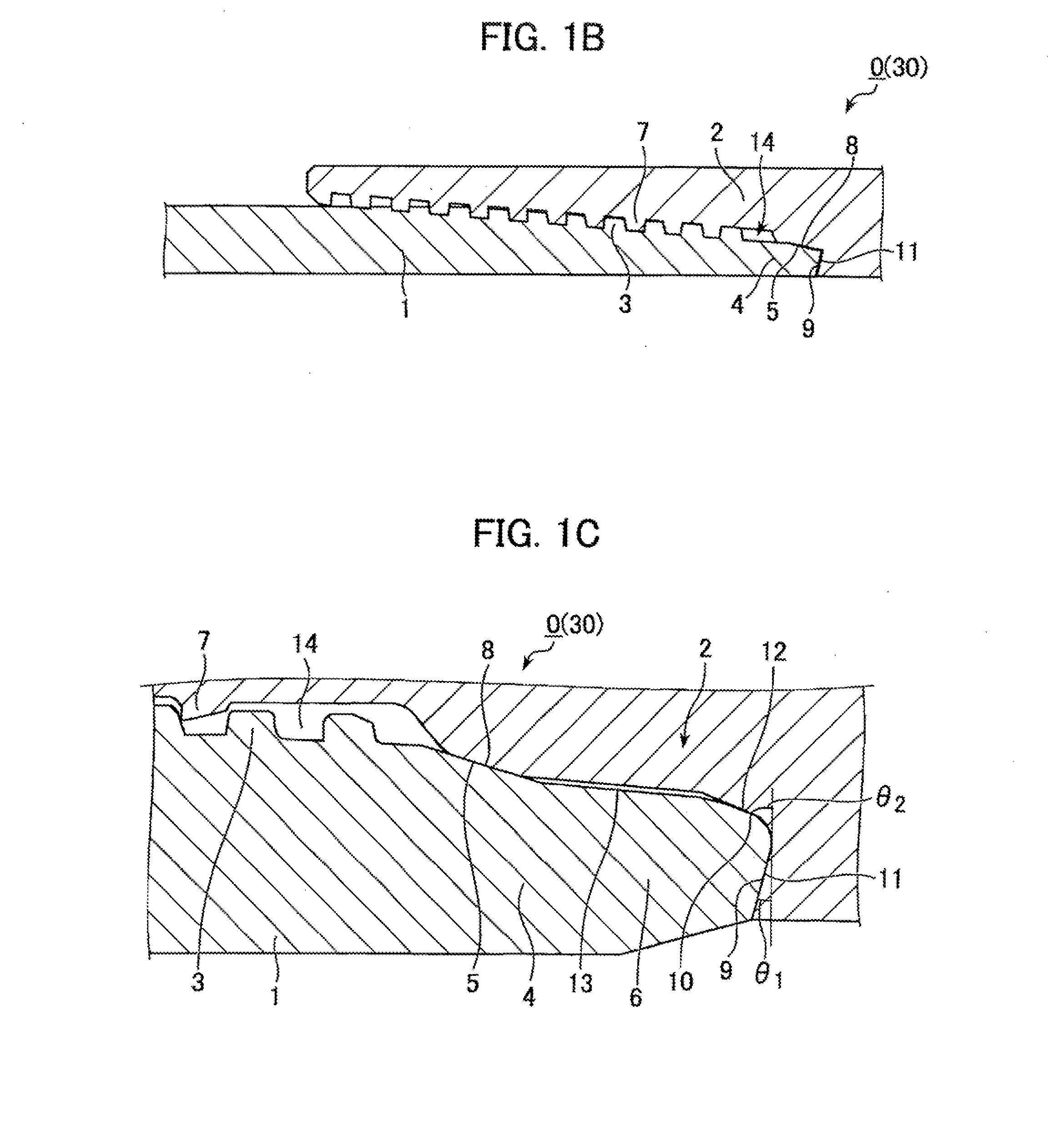
[0124]A seal test (a test in which an internal and external pressure are applied to a threaded joint while a tensile load and a compressive load are applied thereto) was carried out using threaded joints for pipes having the dimensions shown in Table 1. The threaded joints had the shape shown in FIGS. 1A-1C and FIGS. 2A and 2B with grooves 9a formed on the shoulder surfaces having the width and depth shown in Table 1.

[0125]The pin 1 and the box 2 of each of the threaded joints for pipes being tested had contact surfaces constituted by threaded portions 3,7, sealing surfaces 5, 8, and shoulder surfaces, and formed a non-contacting region 13 between the sealing surfaces and the shoulder surfaces. The axial length of the sealing surfaces was 3-5 mm and that of the non-contacting region was 5-15 mm. As shown in FIG. 1C, the shoulder surfaces had main shoulder surfaces 9, 11 and sub-shoulder surfaces 10, 12. The radial thickness (in the direction perpendicular to the pipe axis) of the ma...


PUM


Abstract

A threaded joint for pipes comprises a pin and a box, each having a threaded and unthreaded portion metal contact surface. The unthreaded metal contact portion includes a sealing surface and a shoulder surface, the shoulder surface of the pin located on the pin end surface. A non-contacting region where the pin and the box do not contact each other exists between the sealing surfaces and the shoulder surfaces of the pin and the box. One or more grooves is formed in at least one of the pin and the box shoulder surfaces and extending to the non-contacting region and to the interior of the joint. At least one of the contact surfaces has a solid lubricating coating exhibiting plastic or viscoplastic rheological behavior. A total volume V (mm3) of the grooves and coating weight W (g) of the solid lubricating coating satisfy the equation V/W≧24 (mm3/g).

Description

TECHNICAL FIELD[0001]This invention relates to a threaded joint for pipes (also called a tubular threaded joint) suitable for connecting oil country tubular goods and having grooves on its shoulder surface in order to allow a high pressure fluid to escape. Specifically, it relates to a threaded joint for pipes which prevents a deterioration in to the performance of the grooves by a solid lubricant coating.BACKGROUND ART[0002]In recent years, oil wells are being deeper and are being developed in increasingly severe environments. For this reason, there is a strong desire that tubular threaded joints which are used to connect oil country tubular goods including tubing and casing for oil or gas wells have increased resistance to compression under internal and external pressures and improved sealing properties.[0003]FIG. 1A is a cross-sectional view schematically showing the structure of a typical threaded joint for pipes, FIG. 1B is an enlarged schematic cross-sectional view of portion ...

Claims


Application Information

Patent Timeline
Patent Type & Authority Applications(United States)
IPC IPC(8): E21B17/08F16L15/00
CPCE21B17/08F16L15/004C10M171/00C10M2201/042C10M2201/062C10M2205/022C10M2205/0225C10M2205/183C10M2207/026C10M2207/1253C10M2209/084C10M2229/041C10N2210/05F16L58/182C10M2205/18C10N2010/04E21B17/042C10N2010/10C10N2010/08
Inventor OSHIMA, MASAHIROUGAI, SHINOKADA, TAKASHISASAKI, MASAYOSHIYAMAGUCHI, SUGURUSUGINO, MASAAKI
Owner NIPPON STEEL CORP
Why Eureka
Try Eureka