System stabilization device

a technology of system stability and stabilizer, which is applied in the direction of electric power transfer ac network, greenhouse gas reduction, transportation and packaging, etc., can solve the problems of power failure, frequency drift continues for a while, and adversely affects the power frequency, so as to suppress the change of power frequency and not adversely affect the power frequency

Active Publication Date: 2015-01-01
MITSUBISHI ELECTRIC CORP
View PDF0 Cites 18 Cited by
  • Summary
  • Abstract
  • Description
  • Claims
  • Application Information

AI Technical Summary

Benefits of technology

[0012]According to the present invention, the rate-of-change limit value indicating a limit to be imposed on the total value of changes in the overall output of the first power generators in operation is obtained on the basis of the ever-changing operation information regarding the first power generators, and the command value to be given to the first storage battery is generated on the basis of the interconnection point power flow value and the rate-of-change lim

Problems solved by technology

However, a significant deviation of the power frequencies from a prescribed value may adversely affect consumer's equipment, and yet it is expected that a more significant deviation may have an influence on power generation facilities, and in the worst case, may cause a power failure.
However, since such control is generally performed after a delay and is thus too late when the rate of change in supply-and-demand balance exceeds a threshold va

Method used


Image

  • System stabilization device
  • System stabilization device
  • System stabilization device

Examples


first embodiment

[0032]Before giving a description of power system stabilizers according to embodiments of the present invention, a power system stabilizer related thereto (hereinafter, referred to as a “relevant power system stabilizer”) will be described.

[0033]FIG. 15 is a block diagram showing configurations of the relevant power system stabilizer and a power-system stabilization system that includes the relevant power system stabilizer. As shown in FIG. 15, a relevant power system stabilizer 81, a plurality of power generators 82, and a storage battery 83 are connected to an electric power system 85 via a tie-line 84. The electric power system 85 discussed here is assumed to be a small-scale independent system for power supply provided in an isolated island, and the relevant power system stabilizer 81, the power generators 82, and the storage battery 83 constitute a distributed power distribution system (micro grid) that is responsible for some functions of the electric power system 85.

[0034]The...

second embodiment

[0073]For the above-described relevant power system stabilizer 81 shown in FIG. 15, there has recently been proposed control in which the interconnection point power flow value (the total value of the outputs of the power generators 82 and the storage battery 83 on the tie-line 84) is detected at the time of system interconnection, and a change in power flow due to fluctuations in load or in the output of a distributed power source inside the micro grid is smoothed by using the storage battery 83.

[0074]In actual operations, however, the electric power system 85 is not only connected to the local power generators 82 via the tie-line 84, but also connected to external power generators via another tie-line different from the tie-line 84. In such a configuration, if the supply-and-demand balance of the entire electric power system 85 changes, not only the local power generators 82 but also the external power generators will respond to the change.

[0075]Thus, in order to stabilize the sup...

third embodiment

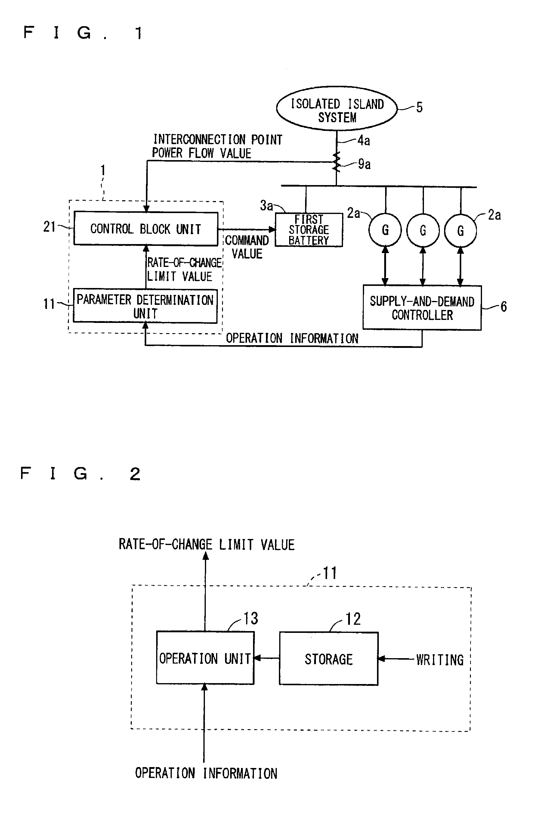
[0098]FIG. 14 is a block diagram showing configurations of a power system stabilizer according to the present embodiment and a power-system stabilization system that includes the power system stabilizer of the present embodiment. Note that in the power system stabilizer and so on according to the present embodiment, constituent elements that are the same as or similar to those described in the second embodiment are denoted by the same reference numerals, and the following description focuses on differences from the second embodiment.

[0099]In the present embodiment, as in the configuration of the second embodiment, the power system stabilizer 1, a plurality of first power generators 2a, and a first storage battery 3a are connected to an isolated island system 5 via a first tie-line 4a, and a plurality of second power generators 2b are connected to the isolated island system 5 via a second tie-line 4b. However, the configuration of the present embodiment differs from that of the secon...


PUM


Abstract

A technique with which a change in power frequency can be suppressed. A power system stabilizer issues a control command to a first storage battery among a plurality of first power generators and the first storage battery that are connected to an isolated island system via a first tie-line. The power system stabilizer includes a parameter determination unit and a control block unit. The parameter determination unit obtains, on the basis of operation information, a rate-of-change limit value that indicates a limit to be imposed on a total value of changes in the overall output of first power generators in operation. The control block unit generates a command value to be given to the first storage battery on the basis of an interconnection point power flow value measured on the first tie-line and the rate-of-change limit value obtained by the parameter determination unit.

Description

TECHNICAL FIELD[0001]The present invention relates to a power system stabilizer that issues a control command to a storage battery among a plurality of power generators and the storage battery that are connected via a tie-line to an independent power supply system provided in, for example, an isolated island.BACKGROUND ART[0002]Power plants adjust the supply of electric power from power generators in accordance with ever-changing electric power demand. The phase “changing electric power demand” as used herein includes not only fluctuations in the amount of electric power consumed by a consumer, but also fluctuations in the amount of natural energy generation such as wind power generation or photovoltaic power generation in power plants built by a consumer or a power generation dealer, and fluctuations due to accidental disconnection.[0003]Frequencies of electric power supplied from power generators are characterized in that they decrease with increasing demand and increase with decr...

Claims


Application Information

Patent Timeline
IPC IPC(8): H02J4/00G06G7/14
CPCG06G7/14H02J4/00H02J3/40Y10T307/549H02J3/34H02J3/32H02J3/48H02J2300/20H02J3/381H02J3/46H02J3/241Y02E70/30
Inventor KOJIMA, YASUHIROTAKAGUCHI, YUSUKEKOSHIO, MASANOBUMARMIROLI, MARTA
Owner MITSUBISHI ELECTRIC CORP
Why Eureka
Try Eureka