Method of energy harvesting using built-in potential difference of metal-to-metal junctions and device thereof

a technology of metal-to-metal junction and energy harvesting, which is applied in the direction of hydro energy generation, electrical apparatus, electrostatic generator/motor, etc., can solve the problems of increasing the design complexity and implementation cost, increasing the cost of implementation, and affecting the design of rectifying electronics

Active Publication Date: 2015-01-01
ARDANUC MEHMET SERHAN +3
View PDF8 Cites 24 Cited by
  • Summary
  • Abstract
  • Description
  • Claims
  • Application Information

AI Technical Summary

Benefits of technology

[0021]Energy harvester related with this invention eliminate

Problems solved by technology

Unfortunately, high-quality piezoelectric crystals are often made from expensive materials, which is an important drawback for large area deployment.
However, these devices need to be pre-charged increasing the design complexity and cost of implementation.
Furthermore, very high output impedance of these devices brings a considerable challenge in the design of the rectifying electronics.
Movement of the plates causes a change in charge or voltage, which results in energy production.
Although this device is shown to work in theory and simulation, no experimental results are presented in the cited paper.
As such, common requirements of vibration to electrical energy conversion in real life situations, which often demands response to broadband and low frequency (<100 Hz) vibrations, are not addressed.
Furthermore, the device mentioned by Kuehne et al. may not be able to achieve power scaling by direct wiring (ie. parallel connection) of similar devices, since asynchronous vibration of different devices connected in parallel can cause cancellation of the outputs of the individual devices.
Although there are lots of energy harvesting methods and devices, it is hard to fin

Method used


Image

  • Method of energy harvesting using built-in potential difference of metal-to-metal junctions and device thereof
  • Method of energy harvesting using built-in potential difference of metal-to-metal junctions and device thereof
  • Method of energy harvesting using built-in potential difference of metal-to-metal junctions and device thereof

Examples


Embodiment Construction

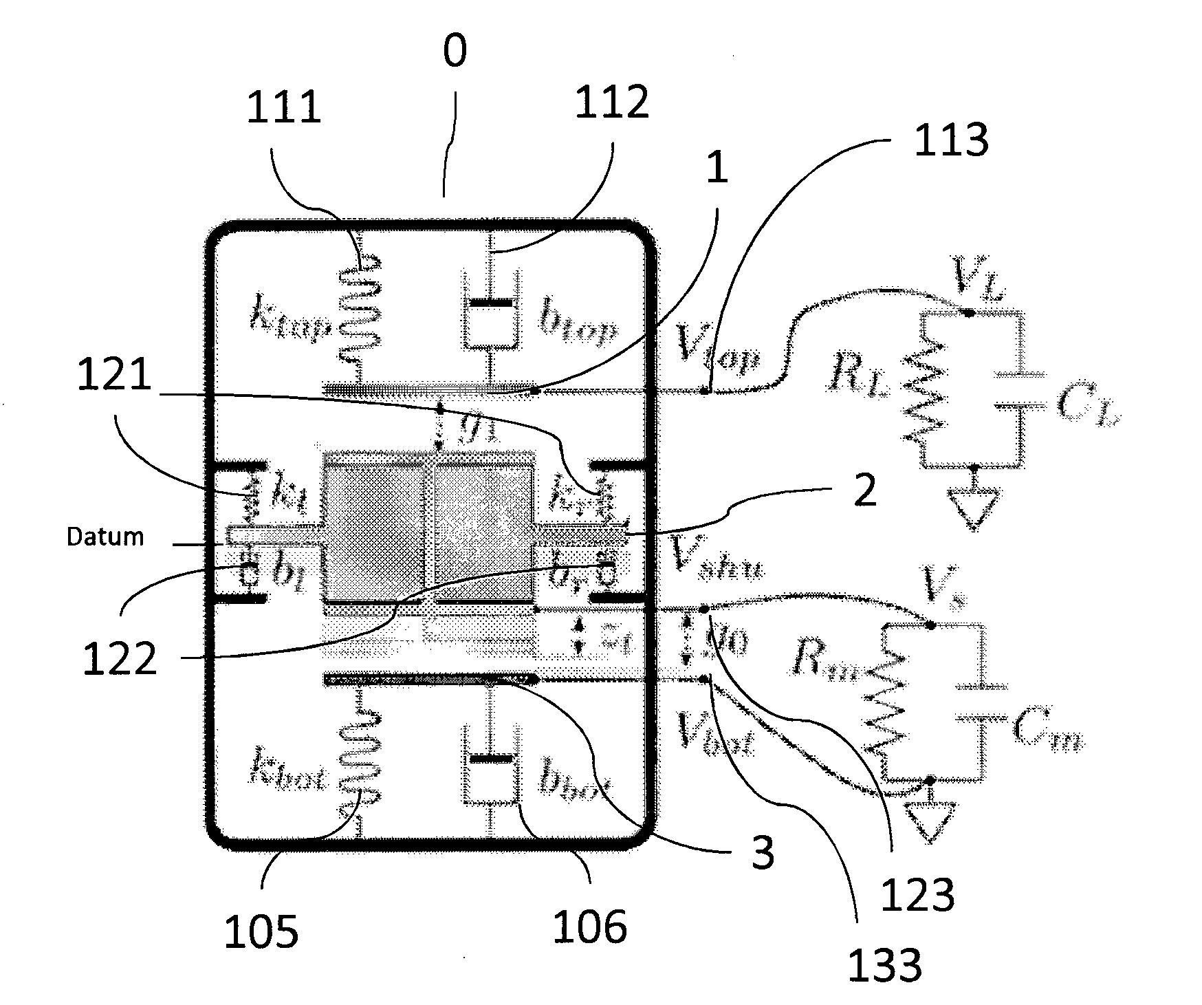
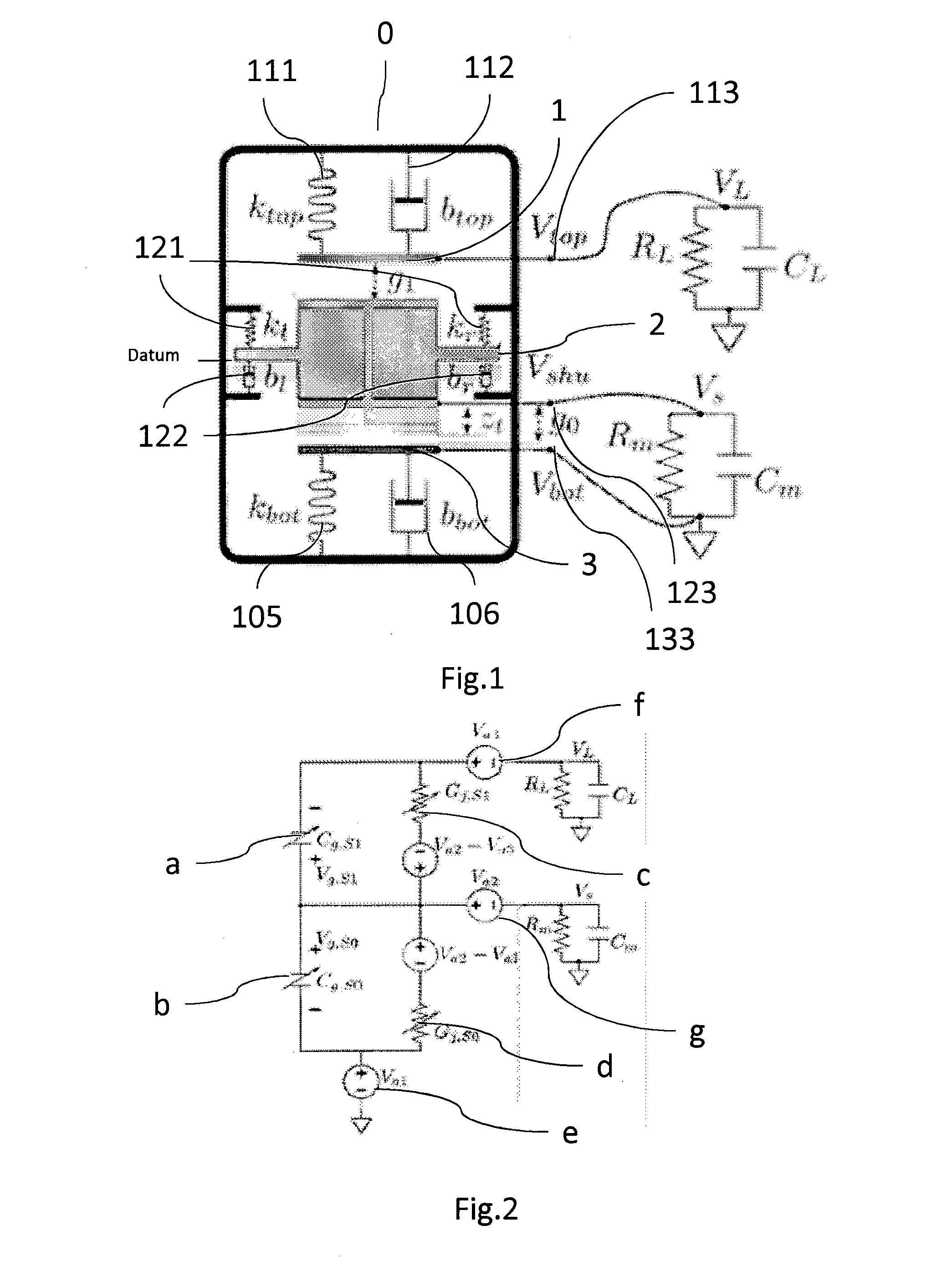
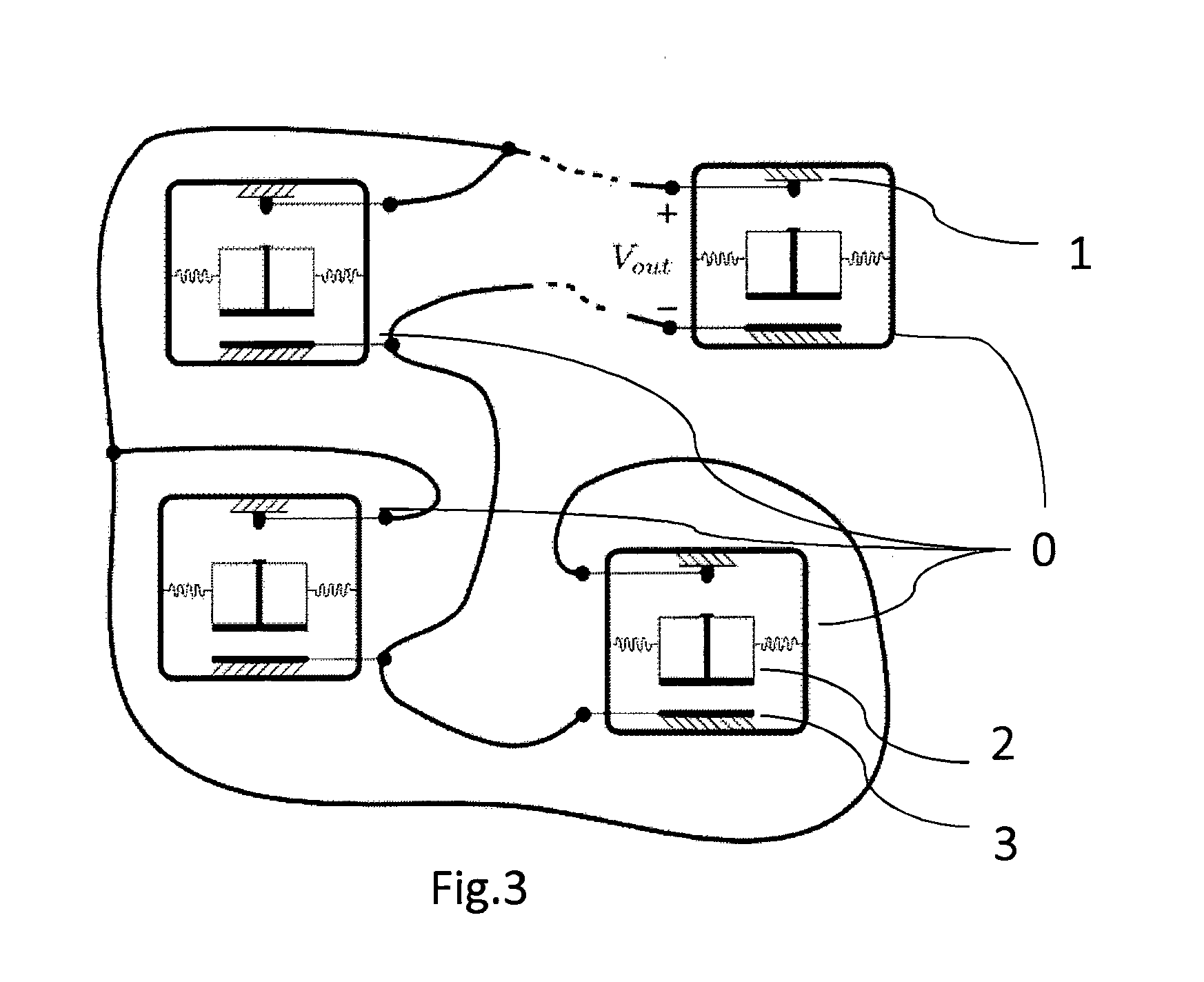
[0059]According to the present invention shown in FIG. 1, the charge Shuttle device (CSD) (0), which is used for kinetic to electrical energy conversion, consists of:[0060]d. One or more moving shuttles (2) and device shuttle nodes (DSN)(123) to transmit and redistribute the charge to the connected load circuit (4).[0061]e. A device first electrode (DFE) (1), on which the amount of electrical charge is affected by the movements of the shuttle(2) in arbitrary directions and amplitude or by the contact of the shuttle (2) and device first electrode node (DFEN)(113) to transmit and redistribute the charge to the circuit,[0062]f. A device second electrode (DSE) which the amount of electrical charge is affected by the movements of shuttle (2) in arbitrary directions and amplitude or by the contact of the shuttle (2) and device second electrode node (DSEN) (133) to transmit and redistribute the charge to the circuit.

[0063]The principle of operation of the charge shuttle device (0) is the c...


PUM


Abstract

This invention is related with electrical energy conversion device, which uses built-in potential of metal-to-metal junctions from repeating movements with random frequencies, speeds and amplitudes at the medium of the device. The device using the method does not rely on a resonant frequency, besides, it can convert the kinetic energy to electrical energy even at low frequencies. Furthermore, its application to the real life situations is economic and beneficial because of the efficient working principle and simple structure. Unique design of the device enables direct wiring of the outputs of identical or similar devices together for the purpose of power scaling without the need of using another device, which may cause energy losses and increase the total cost. This device also does not require a dummy voltage source or a precharge at the beginning of energy harvesting

Description

BACKGROUND OF THE INVENTION[0001]This invention describes a mechanical to electrical energy conversion device, which uses built-in potential of metal-to-metal junctions to generate varying electrical voltages / currents from vibrations or rotations that have random frequencies, speeds, phases and amplitudes within the broad operating range of the device. Furthermore, the operation principle of the invention enables direct wiring of many similar devices, leading to direct increase of the harvested energy without being affected by the differences in the vibration or rotation characteristics as above.PRIOR ART ABOUT THE INVENTION (PREVIOUS TECHNIQUE)[0002]Generating energy with stand-alone structures is an appealing, topic with many emerging applications such as monitoring devices and mobile equipment with rechargeable battery. Providing energy to devices and making them self-powered without bulky wires carrying electrical power enables portability, covertness, and ease of dispatchabilit...

Claims


Application Information

Patent Timeline
IPC IPC(8): H02N1/00
CPCH02N1/00H02N1/08H02N1/04Y02E10/20
Inventor ARDANUC, MEHMET SERHANZORLU, OZGEKULAH, HALUKTAYFUN, AKIN
Owner ARDANUC MEHMET SERHAN
Why Eureka
Try Eureka