Magnetic core and magnetic element using same

a magnetic core and core technology, applied in the field of magnetic cores, can solve the problems of large winding region, low magnetic induction intensity, etc., and achieve the effect of reducing the drawbacks of small winding region, small winding wire diameter, and large winding wire diameter

Inactive Publication Date: 2015-01-01
DELTA ELECTRONICS INC
View PDF13 Cites 7 Cited by
  • Summary
  • Abstract
  • Description
  • Claims
  • Application Information

AI Technical Summary

Benefits of technology

[0007]The present disclosure provides a magnetic core and a magnetic element using the same in order to eliminate the drawbacks of smaller space of winding region, smaller diameter of winding wire, large volume and high heat-dissipation difficulty of winding encapsulation, inadequate distance between the winding encapsulation and the bobbin, and the low magnetic induction intensity and the bad performance of the magnetic core consumption.

Problems solved by technology

However, there are still some drawbacks of the magnetic core 1 mentioned above.
Furthermore, under the trends of high efficiency and high power transformers, the lap amount of the coil of the magnetic core and the magnetic element is usually higher, which causes the winding encapsulation too much larger, and even causes the problems of inadequate distance between the winding encapsulation and the bobbin and high temperature and high heat-dissipation difficulty of the winding encapsulation.
Meanwhile, the diameter of the winding wire of the coil is relatively smaller and not easy to be increased for meeting different demands of practical requirements due to the shape factor of the circle-shaped middle post 12, so the efficiency is not easy to be enhanced at all.

Method used


Image

  • Magnetic core and magnetic element using same
  • Magnetic core and magnetic element using same
  • Magnetic core and magnetic element using same

Examples


Embodiment Construction

[0021]The present disclosure will now be described more specifically with reference to the following embodiments. It is to be noted that the following descriptions of preferred embodiments of this disclosure are presented herein for purpose of illustration and description only. It is not intended to be exhaustive or to be limited to the precise form disclosed.

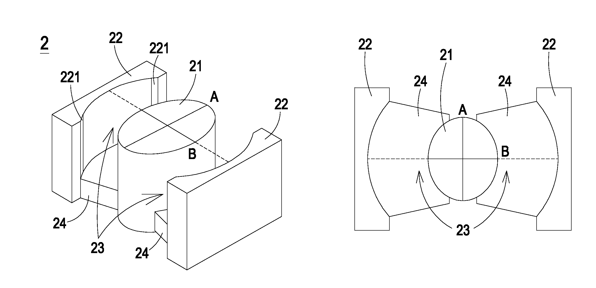
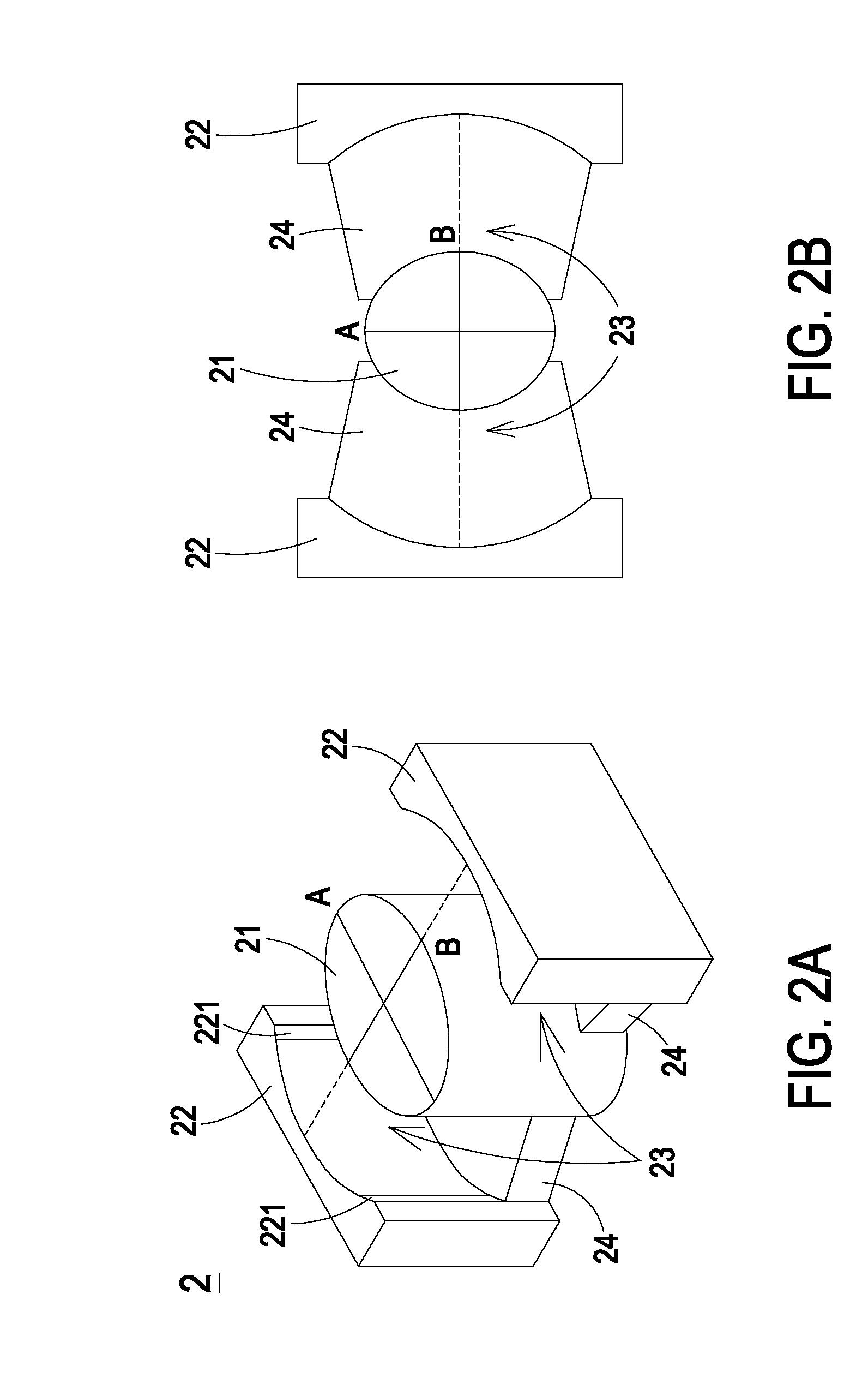
[0022]Please refer to FIG. 2A and FIG. 2B. FIG. 2A schematically illustrates the structure of a magnetic core according to an embodiment of the present disclosure. FIG. 2B schematically illustrates a top view of the magnetic core as shown in FIG. 2A. As shown in FIG. 2A and FIG. 2B, the magnetic core 2 of the present disclosure includes an ellipse-shaped central post 21 and two side posts 22. The ellipse-shaped central post 21 includes a long axis A and a short axis B, among which the length of the long axis A is greater than the length of the short axis B. The two side posts 22 are disposed on the two sides of the ellipse-shap...


PUM

PropertyMeasurementUnit
distanceaaaaaaaaaa
lengthaaaaaaaaaa
volumeaaaaaaaaaa

Abstract

A magnetic core includes an ellipse-shaped central post and two side posts. The ellipse-shaped central post includes a long axis and a short axis. The length of the long axis is greater than the length of the short axis. The two side posts are disposed on two sides of the ellipse-shaped central post and opposite to each other. The two side posts are connected with the ellipse-shaped central post through two connecting portions respectively for defining at least one winding space with the ellipse-shaped central post. By utilizing the ellipse-shaped central post, the volume of the winding space is increased, the diameter of the wire of the winding coil can be increased, the temperature of the winding encapsulation is easy to be lowered, the over-volume issue of the winding encapsulation is avoided, and the safe distance between the bobbin and the winding encapsulation is increased, so that the present disclosure meets the safety regulation.

Description

TECHNICAL FIELD[0001]The present disclosure relates to a magnetic core, and more particularly to a magnetic core including an ellipse-shaped central post and a magnetic element using the same.BACKGROUND[0002]Magnetic elements are the basic components of electronic devices. The magnetic elements are widely utilized to lot types of electronic devices. With the trends of miniaturization, high power, multi functions and popularization, the magnetic elements are flat designed, the performance is required to be enhanced, the structure diversity is required to be promoted, and the costs are required to be reduced.[0003]Please refer to FIG. 1A. FIG. 1A schematically illustrates the structure of a magnetic core of a traditional magnetic element. In general, a magnetic core 1 may include a middle post 11 and two lateral posts 12. A winding region 13 is defined by the middle post 11 and the two lateral posts 12 for a coil to wind around. Please refer to FIG. 1B. FIG. 1B schematically illustrat...

Claims


Application Information

Patent Timeline
Patent Type & Authority Applications(United States)
IPC IPC(8): H01F3/00
CPCH01F3/00H01F27/263H01F3/10
Inventor LIN, HAN-HSINGLAI, YU-CHUNCHEN, YI-LINLIU, CHIA-MINGCHEN, CHIH-MINGLIU, CHIEN-HUNG
Owner DELTA ELECTRONICS INC
Why Eureka
Try Eureka