
Radar transceiver

a transceiver and radar technology, applied in the field of radar transceivers, can solve the problems of large sensor physical size, unsuitable short- and middle-range radar applications, and inability to accurately detect the chirp parameters, and achieve the effect of preventing accidental transmission of chirp parameters

Active Publication Date: 2015-01-01
NXP BV
View PDF6 Cites 16 Cited by
  • Summary
  • Abstract
  • Description
  • Claims
  • Application Information

AI Technical Summary

Benefits of technology

The patent text describes how a timing engine controls the generation of chirps, which are used to synchronize signals in electronic devices. By using a PLL, the sweep control unit can directly control the chirps, resulting in more precise timing. Additionally, the timing engine includes a register that prevents the accidental transmission of chirp parameters. This helps to improve the overall quality and accuracy of the generated chirps.

Problems solved by technology

Lens-antenna based techniques have the disadvantage of a small angular field-of-view of +10 degrees, making this approach less suitable for short- and middle-range radar applications where a larger field of view is required i.e. larger than ±60° degrees.
The large RX antenna array, on the other hand, leads to a large sensor physical size which is a drawback in many practical circumstances e.g. placement behind the bumper, etc.
This is undesirable, because:SPI communications are in general not suitable for precise timing of functional operations, because the generation of control strings relies on software routines running inside the micro-controller;SPI response may have a relatively large latency due to message header overhead, andSPI bus activity during communication can disturb sensitive portions of the radar IC during the data acquisition cycle.

Method used


Image

  • Radar transceiver
  • Radar transceiver
  • Radar transceiver

Examples


Embodiment Construction

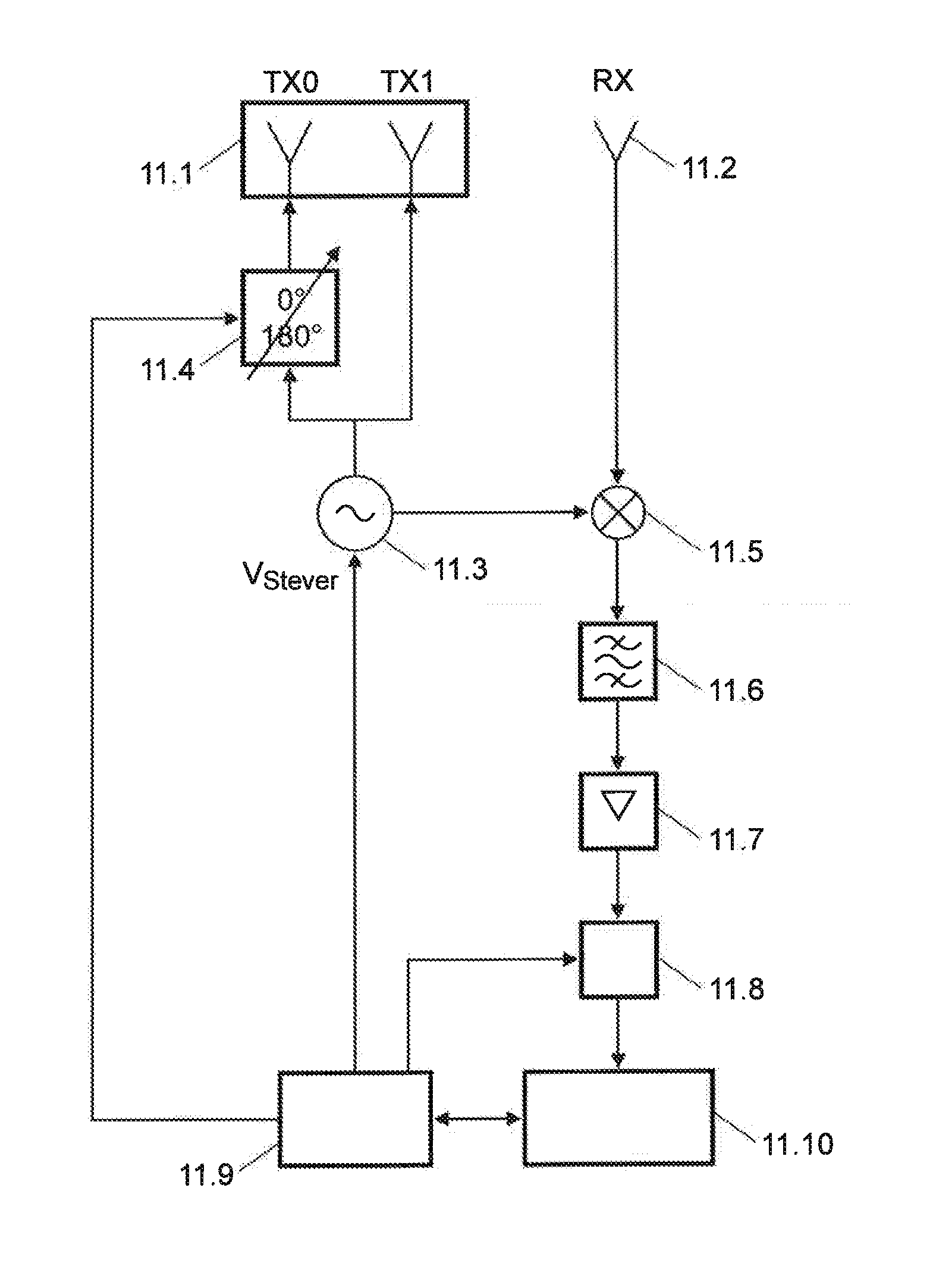
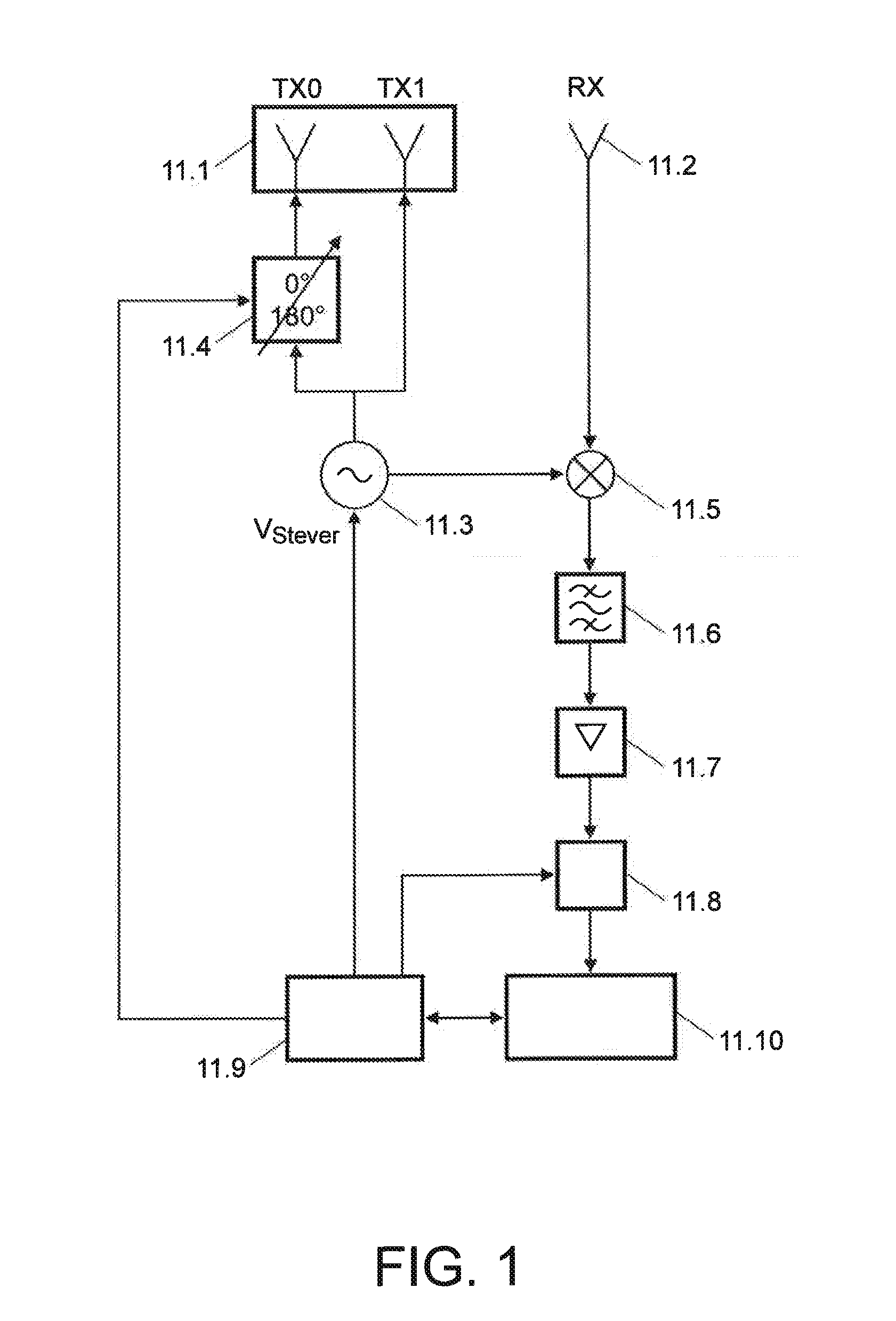
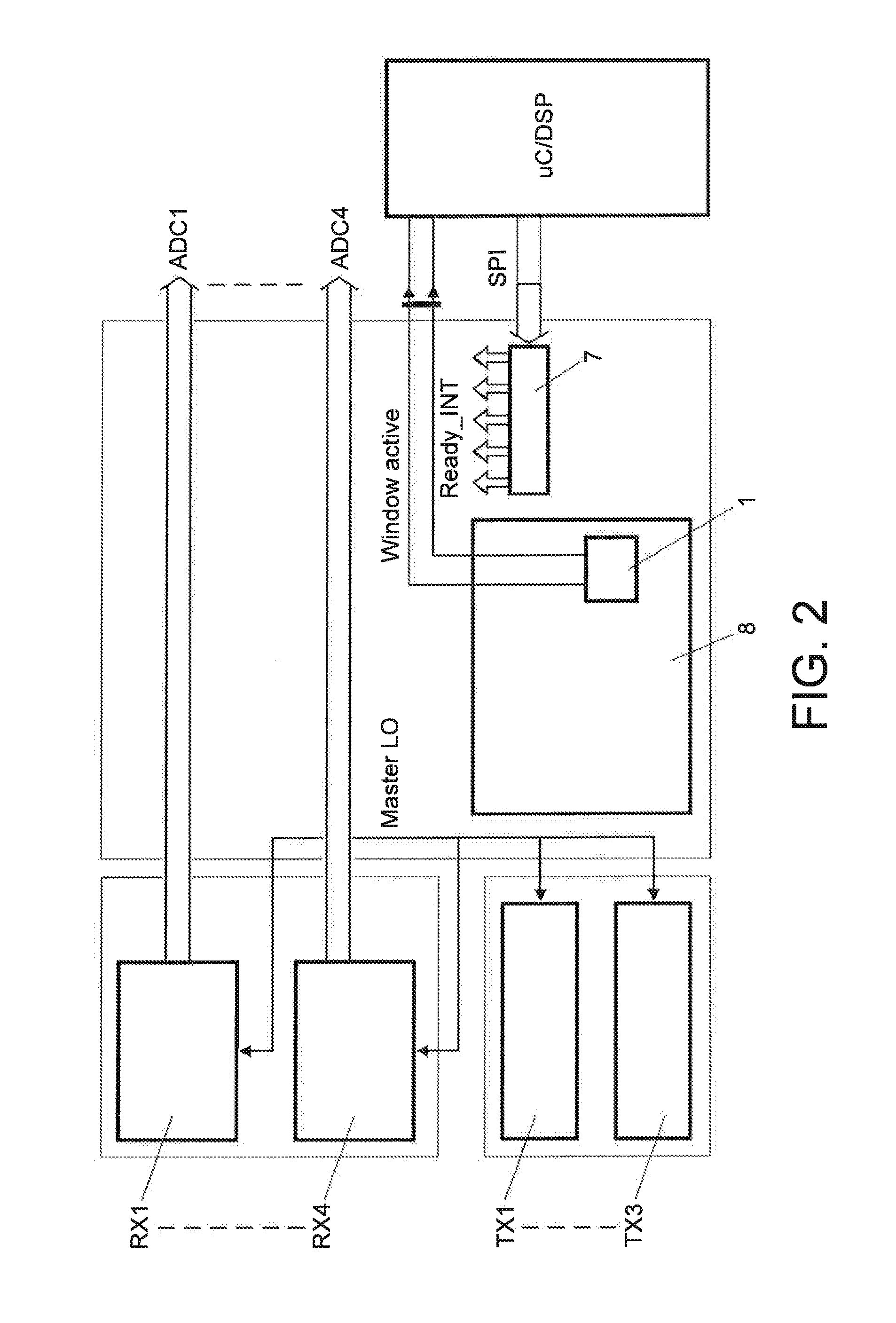
[0067]FIG. 4 depicts a radar system according to an aspect of the application. The radar system comprises a set of transmitters TX1, . . . , TXn for transmitting radar chirps to targets, a set of receivers RX1, . . . , RXn for receiving reflected chirps from the targets and a timing engine 1 coupled to the set of transmitters TX1, . . . , TXn and to the set of receivers RX1, . . . , RXn. The timing engine 1 is adapted to transmit a first set of control signals to the set of transmitters TX1, . . . , TXn and to the set of receivers RX1, . . . , RXn. The timing engine 1 is further coupled to a computing unit 4, the timing engine 1 being adapted to receive a second set of control signals generated by the computing unit 4 and transmitted via a bus. The radar system further comprises a sweep control unit 2 coupled to the timing engine 1 and adapted to receive a first control signal and a second control signal from the timing engine 1, the first control signal indicating a start time of a...


PUM


Abstract

The application refers to a radar transceiver comprising a set of transmitters (TX1, . . . , TXn) for transmitting radar chirps to targets, a set of receivers (RX 1, . . . , RXn) for receiving reflected chirps from the targets, a timing engine (1) coupled to the set of transmitters (TX1, . . . , TXn) and to the set of receivers (RX1, . . . , RXn) and adapted to transmit a first set of control signals to the set of transmitters (TX1, . . . , TXn) and to the set of receivers (RX1, . . . , RXn). The timing engine (1) is further coupled to a computing unit (4). The timing engine (1) is adapted to receive a second set of control signals generated by the computing unit (4) and transmitted via a bus. The radar transceiver further comprises a sweep control unit (2) coupled to the timing engine (1) and adapted to receive a first control signal and a second control signal from the timing engine (1), the first control signal indicating a precise start time of a chirp and the second control signal indicating a precise reset time for resetting the chirp. The sweep control unit (2) is further coupled to a controlled Phase Locked Loop (PLL) (3) adapted to generate a local oscillator (Master LO) signal which is adapted to be inputted to both each member of the set of transmitters (TX1, . . . , TXn) and each member of the set of receivers (RX1, . . . , RXn).

Description

FIELD OF THE INVENTION[0001]The invention relates to a radar transceiver and to a method to operate such a transceiver.BACKGROUND OF THE INVENTION[0002]Radar sensors featuring high angular resolution normally rely on large antenna apertures. This can be achieved with the use of a dielectric lens in front of a small number of antenna elements, or with a large number of receiving (RX) elements in a phased array configuration as e.g. Bosch LRR3. Lens-antenna based techniques have the disadvantage of a small angular field-of-view of +10 degrees, making this approach less suitable for short- and middle-range radar applications where a larger field of view is required i.e. larger than ±60° degrees. In the following description the term RX is used to indicate a receiver and the term TX is used to indicate a transmitter, together with their plural forms RXs and TXs, respectively.[0003]The large RX antenna array, on the other hand, leads to a large sensor physical size which is a drawback in...

Claims


Application Information

Patent Timeline
Patent Type & Authority Applications(United States)
IPC IPC(8): G01S7/02G01S13/02G01S13/931
CPCG01S13/02G01S7/02G01S13/931G01S7/35G01S7/28
Inventor VAUCHER, CICERO SILVEIRAGEHRELS, CORNELIS
Owner NXP BV
Learn More