Head-mount type display device and method of controlling head-mount type display device
- Summary
- Abstract
- Description
- Claims
- Application Information
AI Technical Summary
Benefits of technology
Problems solved by technology
Method used
Image

Examples
first embodiment
A. First Embodiment
A-1. Configuration of Head-Mount Type Display Device
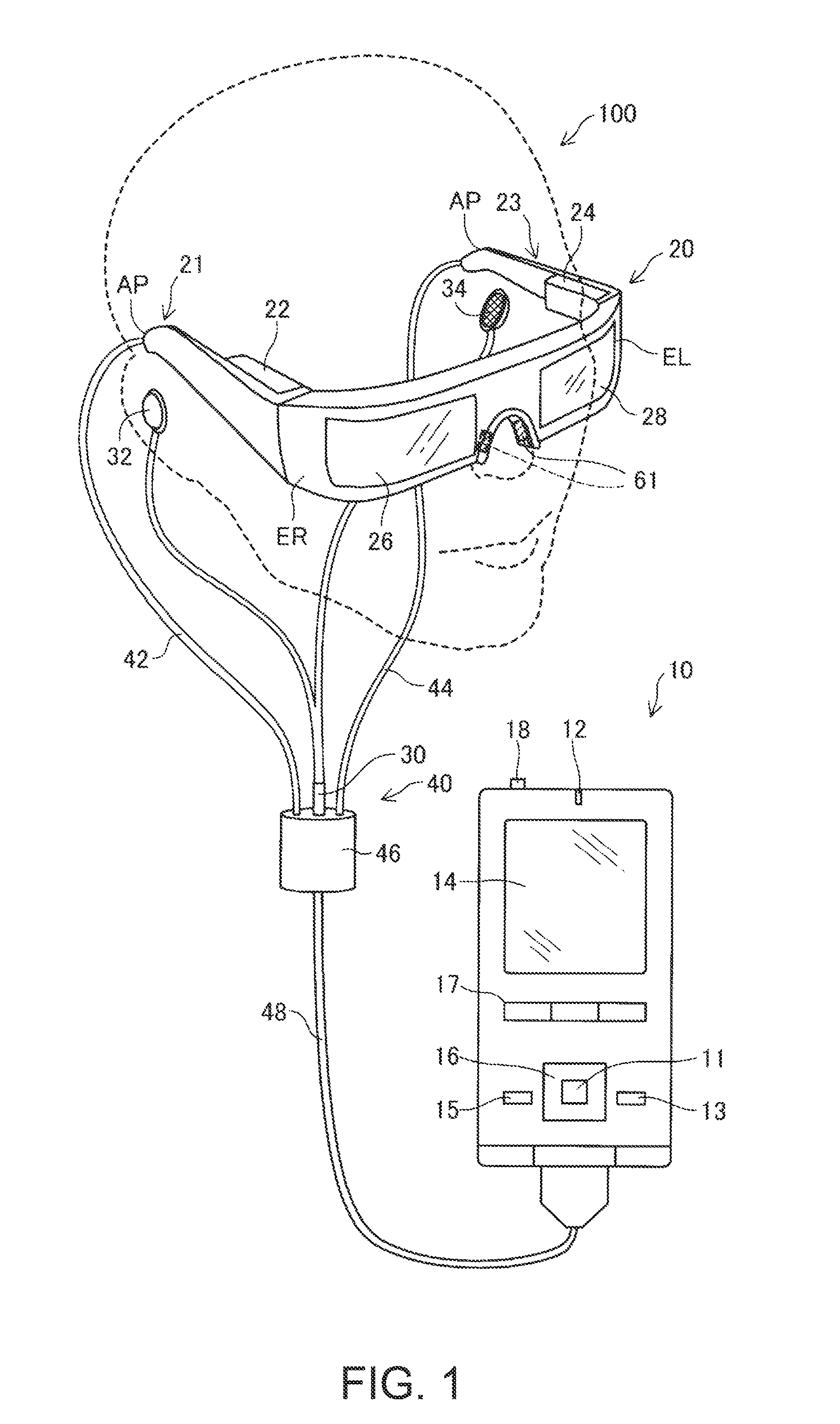
[0052]FIG. 1 is an explanatory diagram showing an exterior configuration of a head-mount type display device 100. The head-mount type display device 100 is a display device to be mounted on the head, and is also called a head mounted display (HMD). The head-mount type display device 100 according to the first embodiment is an optical transmissive head-mount type display device allowing the user to visually recognize a virtual image and at the same time visually recognize an external sight directly. It should be noted that in the present specification, the virtual image to be visually recognized by the user using the head-mount type display device 100 is also referred to as a “display image” for the sake of convenience. Further, emission of the image light generated based on the image data is also referred to as “display of the image.”
[0053]The head-mount type display device 100 is provided with an image display s...
second embodiment
B. Second Embodiment
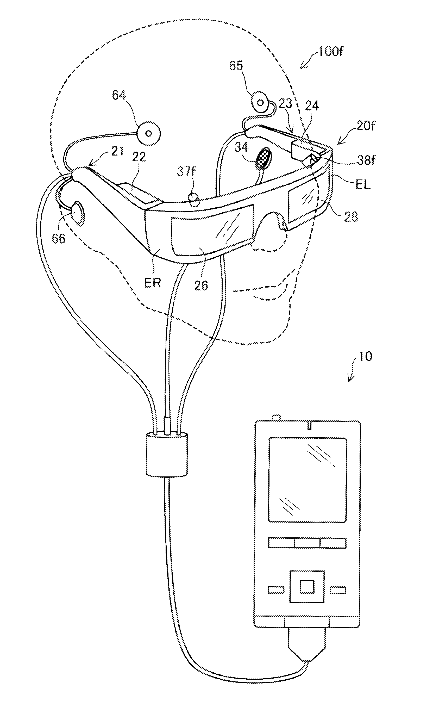
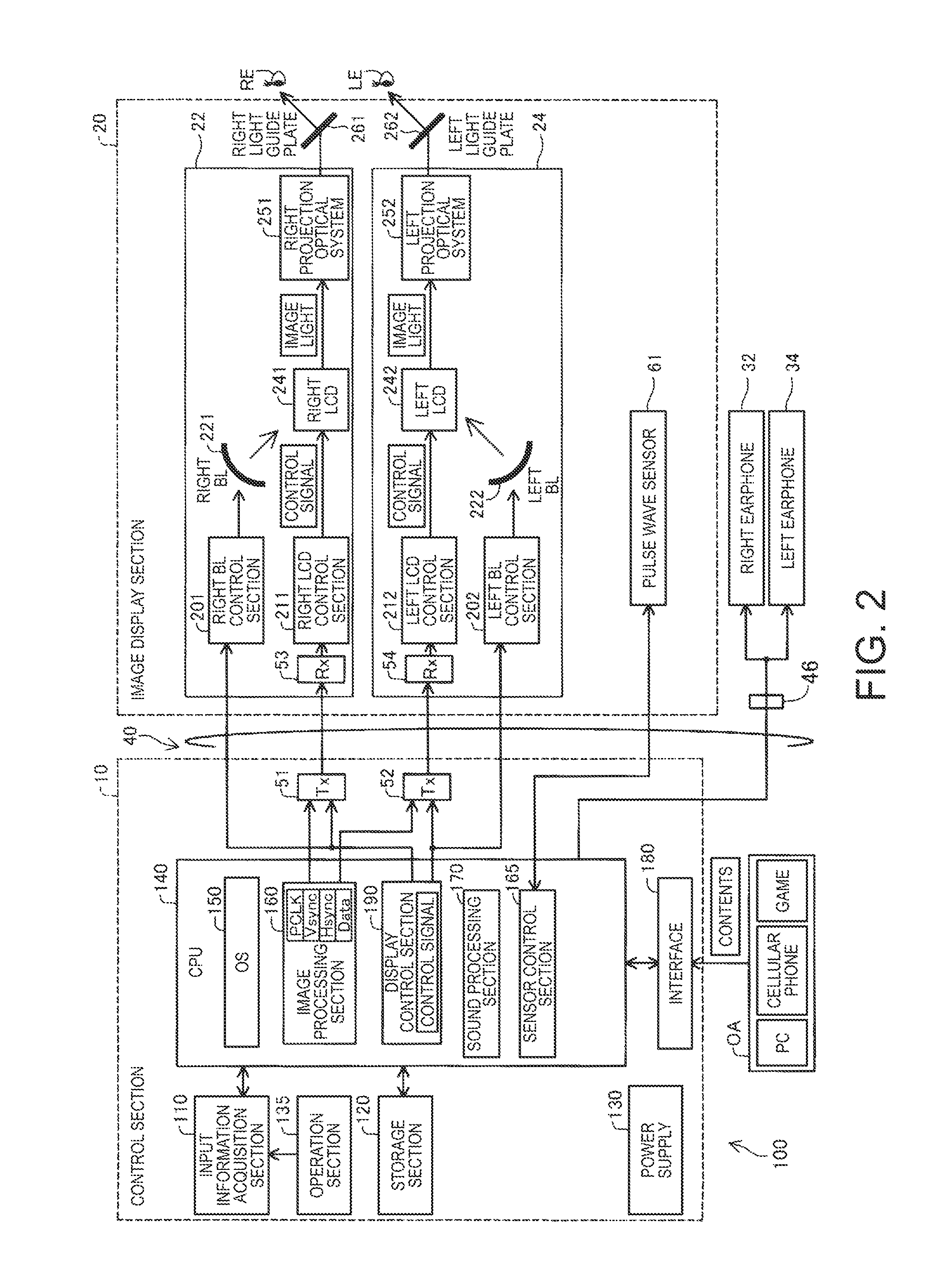
[0094]FIG. 11 is an explanatory diagram showing an exterior configuration of a head-mount type display device 100f according to a second embodiment. FIG. 12 is a block diagram functionally showing a configuration of the head-mount type display device 100f according to the second embodiment. As shown in FIGS. 11 and 12, in the head-mount type display device 100f according to the second embodiment, there are disposed an ear thermometer 66, a right electromyograph 64, a left electromyograph 65, a right-eye imaging camera 37f, and a left-eye imaging camera 38f instead of the pulse wave sensor 61 of the first embodiment. Further, as shown in FIG. 12, a control section 10f of the second embodiment includes a taken-image processing section 166 for processing the images taken by the right-eye imaging camera 37f and the left-eye imaging camera 38f.
[0095]The ear thermometer 66 is a thermometer to be inserted into an earhole of the user to thereby measure the body temperat...
modified example 1
C1. Modified Example 1
[0111]FIGS. 14 and 15 are explanatory diagrams each showing an exterior configuration of a head-mount type display device according to a modified example. The head-mount type display device 100a and the head-mount type display device 100b according to the present modified example are each different in the position at which the pulse wave sensor 61 is disposed in the image display section 20 from the head-mount type display device 100 according to the embodiment described above, and are the same in the other points as in the embodiment described above. As shown in FIG. 14, in the head-mount type display device 100a, the pulse wave sensor 62 is disposed at the position, which faces a portion located above the right ear of the user when the user wears the image display section 20 on the head, and the pulse wave sensor 63 is disposed at the position, which faces a portion located above the left ear of the user. Further, as shown in FIG. 15, in the head-mount type d...
PUM
 Abstract
Description
Claims
Application Information
 - R&D
- Intellectual Property
- Life Sciences
- Materials
- Tech Scout
- Unparalleled Data Quality
- Higher Quality Content
- 60% Fewer Hallucinations
Browse by: Latest US Patents, China's latest patents, Technical Efficacy Thesaurus, Application Domain, Technology Topic, Popular Technical Reports.
© 2025 PatSnap. All rights reserved.Legal|Privacy policy|Modern Slavery Act Transparency Statement|Sitemap|About US| Contact US: help@patsnap.com